User Guide
Page 4
... uip men t h as been tested and found to comply with the limits for a Class B digital device, pursuant to Part 15 of the FCC Rules. Micro-Star International MS-7508 This device complies with Part 15 of the FCC Rules. Operation is encouraged to try to correct the interference by one or more of...
... uip men t h as been tested and found to comply with the limits for a Class B digital device, pursuant to Part 15 of the FCC Rules. Micro-Star International MS-7508 This device complies with Part 15 of the FCC Rules. Operation is encouraged to try to correct the interference by one or more of...
User Guide
Page 11
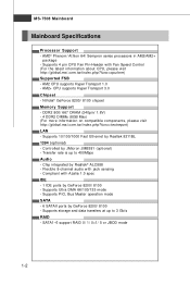
MS-7508 Mainboard Mainboard Specifications Processor Support - ms i. Supports 10/100/1000 Fast Ethernet by JMicron JMB381 (optional) - Compliant with Fan Speed Control (For the latest information about CPU, please visit ht t p: / / g loba l. ... 1.0 - p hp?f unc =t e s t re por t ) LAN - Chip integrated by GeForce 8200/ 8100 - Flexible 8-channel audio with jack sensing - t w / i ndex . t w / i nde x . php?f unc = c puf orm) Supported FSB - ms i .
MS-7508 Mainboard Mainboard Specifications Processor Support - ms i. Supports 10/100/1000 Fast Ethernet by JMicron JMB381 (optional) - Compliant with Fan Speed Control (For the latest information about CPU, please visit ht t p: / / g loba l. ... 1.0 - p hp?f unc =t e s t re por t ) LAN - Chip integrated by GeForce 8200/ 8100 - Flexible 8-channel audio with jack sensing - t w / i ndex . t w / i nde x . php?f unc = c puf orm) Supported FSB - ms i .
User Guide
Page 13
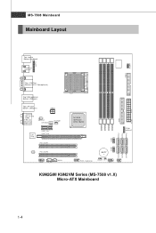
... DIMM3 DIMM4 JTPM1 (o pt ional ) SATA2 SATA3 SATA5 JUSB2 JUSB1 SATA1 SATA4 SATA6 J13 94_1(opt ional) BAT T + JVBAT1 J CI1 JFP1 JFP2 K9N2GM/ K9N2VM Series (MS-7508 v1.X) Micro-ATX Mainboard IDE1 ATX1 1-4 MS-7508 Mainboard Mainboard Layout JC OM1 JLPT1 Top : mouse Bottom: keyboard HDMI Port (optional) FDD 1 Top : VGA Port Bottom: DVI-D Port(optional) Top...
... DIMM3 DIMM4 JTPM1 (o pt ional ) SATA2 SATA3 SATA5 JUSB2 JUSB1 SATA1 SATA4 SATA6 J13 94_1(opt ional) BAT T + JVBAT1 J CI1 JFP1 JFP2 K9N2GM/ K9N2VM Series (MS-7508 v1.X) Micro-ATX Mainboard IDE1 ATX1 1-4 MS-7508 Mainboard Mainboard Layout JC OM1 JLPT1 Top : mouse Bottom: keyboard HDMI Port (optional) FDD 1 Top : VGA Port Bottom: DVI-D Port(optional) Top...

User Guide
Page 18
... mainboard. Look for Socket AM2/ AM2+ 1. Gold arrow 4. Pull the lever sideways away from the socket. Lower the CPU down the CPU Close the lever 2-4 MS-7508 Mainboard CPU Installation Procedures for the gold arrow on top of the correct installation procedures may cause permanent damages to a 90-degree angle. Please turn...
... mainboard. Look for Socket AM2/ AM2+ 1. Gold arrow 4. Pull the lever sideways away from the socket. Lower the CPU down the CPU Close the lever 2-4 MS-7508 Mainboard CPU Installation Procedures for the gold arrow on top of the correct installation procedures may cause permanent damages to a 90-degree angle. Please turn...
User Guide
Page 20
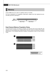
...112 pin 64x2=128 pin Dual-Channel Memory Population Rules In Dual-Channel mode, the memory modules can enhance the system performance. MS-7508 Mainboard Memory These DIMM slots are used for Dual-Channel mode. 1 DIMM1 DIMM2 DIMM3 DIMM4 2 DIMM1 DIMM2 DIMM3 DIMM4 Installed ...Empty 2-6 For more information on compatible components, please visit http://global.msi.com. Enabling Dual-Channel mode can transmit and receive data with two data bus lines simultaneously. The following illustrations explain the ...
...112 pin 64x2=128 pin Dual-Channel Memory Population Rules In Dual-Channel mode, the memory modules can enhance the system performance. MS-7508 Mainboard Memory These DIMM slots are used for Dual-Channel mode. 1 DIMM1 DIMM2 DIMM3 DIMM4 2 DIMM1 DIMM2 DIMM3 DIMM4 Installed ...Empty 2-6 For more information on compatible components, please visit http://global.msi.com. Enabling Dual-Channel mode can transmit and receive data with two data bus lines simultaneously. The following illustrations explain the ...
User Guide
Page 22
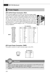
...the connectors are aligned. Power supply of 350 watts (and above) is inserted in the proper orientation and the pins are connected to proper ATX power supplies to ensure stable operation of the power supply is highly recommended for system stability. 2-8 Pin Definition 12 24 PIN SIGNAL PIN SIGNAL... plug your power supply along with pin 1 & pin 13 (refer to connect an ATX 24-pin power supply. If you'd like to use the 20-pin ATX power supply as you like. MS-7508 Mainboard Power Supply ATX 24-Pin Power Connector: ATX1 This connector allows you to the image at the right...
...the connectors are aligned. Power supply of 350 watts (and above) is inserted in the proper orientation and the pins are connected to proper ATX power supplies to ensure stable operation of the power supply is highly recommended for system stability. 2-8 Pin Definition 12 24 PIN SIGNAL PIN SIGNAL... plug your power supply along with pin 1 & pin 13 (refer to connect an ATX 24-pin power supply. If you'd like to use the 20-pin ATX power supply as you like. MS-7508 Mainboard Power Supply ATX 24-Pin Power Connector: ATX1 This connector allows you to the image at the right...

User Guide
Page 24
DVI-D Port (optional) The DVI-D (Digital Visual Interface-Digital) connector allows you power-on the system. MS-7508 Mainboard Back Panel Mouse (optional) HDMI Port Keyboard VGA Port (optional) LAN 1394 Port Line-In RS-Out Line-Out CS-Out DVI-D Port (optional) ...
DVI-D Port (optional) The DVI-D (Digital Visual Interface-Digital) connector allows you power-on the system. MS-7508 Mainboard Back Panel Mouse (optional) HDMI Port Keyboard VGA Port (optional) LAN 1394 Port Line-In RS-Out Line-Out CS-Out DVI-D Port (optional) ...

User Guide
Page 26
Refer to master / slave mode by the vendors for jumper setting instructions. 2-12 IDE1 Important If you install two IDE devices on the same cable, you must configure the drives separately to IDE device's documentation supplied by setting jumpers. FDD1 IDE Connector: IDE1 This connector supports IDE hard disk drives, optical disk drives and other IDE devices. MS-7508 Mainboard Connectors Floppy Disk Drive Connector: FDD1 This connector supports 360KB, 720KB, 1.2MB, 1.44MB or 2.88MB floppy disk drive.
Refer to master / slave mode by the vendors for jumper setting instructions. 2-12 IDE1 Important If you install two IDE devices on the same cable, you must configure the drives separately to IDE device's documentation supplied by setting jumpers. FDD1 IDE Connector: IDE1 This connector supports IDE hard disk drives, optical disk drives and other IDE devices. MS-7508 Mainboard Connectors Floppy Disk Drive Connector: FDD1 This connector supports 360KB, 720KB, 1.2MB, 1.44MB or 2.88MB floppy disk drive.
User Guide
Page 28
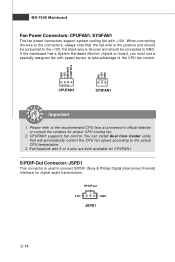
MS-7508 Mainboard Fan Power Connectors: CPUFAN1, SYSFAN1 The fan power connectors support system cooling fan with 3 or 4 pins are both available for CPUFAN1. CPUFAN1 supports fan ...
MS-7508 Mainboard Fan Power Connectors: CPUFAN1, SYSFAN1 The fan power connectors support system cooling fan with 3 or 4 pins are both available for CPUFAN1. CPUFAN1 supports fan ...

User Guide
Page 30
... PIN SIGNAL 1 VCC 3 USB0- 5 USB0+ 7 GND 9 Key (no pin) PIN SIGNAL 2 VCC 4 USB1- 6 USB1+ 8 GND 10 NC Important Note that sends/receives 16 bytes FIFOs. MS-7508 Mainboard Front USB Connector: JUSB1/ JUSB2 This connector, compliant with Intel® I/O Connectivity Design Guide, is a 16550A high speed communication port that the pins of...
... PIN SIGNAL 1 VCC 3 USB0- 5 USB0+ 7 GND 9 Key (no pin) PIN SIGNAL 2 VCC 4 USB1- 6 USB1+ 8 GND 10 NC Important Note that sends/receives 16 bytes FIFOs. MS-7508 Mainboard Front USB Connector: JUSB1/ JUSB2 This connector, compliant with Intel® I/O Connectivity Design Guide, is a 16550A high speed communication port that the pins of...

User Guide
Page 32
... Definition PIN SIGNAL 1 GND 2 SPK- 3 SLED 4 BUZ+ 5 PLED 6 BUZ- 7 NC 8 SPK+ DESCRIPTION Ground SpeakerSuspend LED Buzzer+ Power LED BuzzerNo connection Speaker+ 2-18 Do not use. MS-7508 Mainboard Front Panel Connectors: JFP1, JFP2 These connectors are for electrical connection to GND Reserved. The JFP1 is compliant with Intel® Front Panel I/O Connectivity...
... Definition PIN SIGNAL 1 GND 2 SPK- 3 SLED 4 BUZ+ 5 PLED 6 BUZ- 7 NC 8 SPK+ DESCRIPTION Ground SpeakerSuspend LED Buzzer+ Power LED BuzzerNo connection Speaker+ 2-18 Do not use. MS-7508 Mainboard Front Panel Connectors: JFP1, JFP2 These connectors are for electrical connection to GND Reserved. The JFP1 is compliant with Intel® Front Panel I/O Connectivity...

User Guide
Page 34
... that comply with PCI specifications. 32-bit PCI Slot Important When adding or removing expansion cards, make sure that you unplug the power supply first. MS-7508 Mainboard Slots PCI-E (Peripheral Component Interconnect-Express) Slot The PCI Express slot supports the PCI Express interface expansion card.
... that comply with PCI specifications. 32-bit PCI Slot Important When adding or removing expansion cards, make sure that you unplug the power supply first. MS-7508 Mainboard Slots PCI-E (Peripheral Component Interconnect-Express) Slot The PCI Express slot supports the PCI Express interface expansion card.
User Guide
Page 36
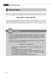
... digit refers to the chipset as I = Intel, N = nVidia, and V = VIA. 7th - 8th digit refers to enter Setup, restart the system by simultaneously pressing , , and keys. MS-7508 Mainboard Entering Setup Power on the screen, press key to enter Setup. The items under continuous update for reference only. 2. Therefore, the description may also... (Power On Self Test) process. Press DEL to enter SETUP If the message disappears before you respond and you still wish to the customer as MS = all standard customers. Important 1.
... digit refers to the chipset as I = Intel, N = nVidia, and V = VIA. 7th - 8th digit refers to enter Setup, restart the system by simultaneously pressing , , and keys. MS-7508 Mainboard Entering Setup Power on the screen, press key to enter Setup. The items under continuous update for reference only. 2. Therefore, the description may also... (Power On Self Test) process. Press DEL to enter SETUP If the message disappears before you respond and you still wish to the customer as MS = all standard customers. Important 1.
User Guide
Page 38
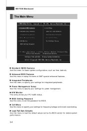
... Use this menu to specify your settings for frequency/voltage control and overclocking. Cell Menu Use this menu to specify your settings for power management. MS-7508 Mainboard The Main Menu Standard CMOS Features Use this menu for integrated peripherals. Advanced BIOS Features Use this menu to setup the items of AMI...
... Use this menu to specify your settings for frequency/voltage control and overclocking. Cell Menu Use this menu to specify your settings for power management. MS-7508 Mainboard The Main Menu Standard CMOS Features Use this menu for integrated peripherals. Advanced BIOS Features Use this menu to setup the items of AMI...
User Guide
Page 40
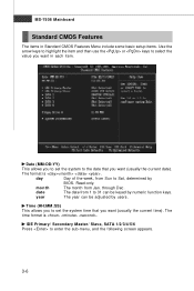
... format is . IDE Primary/ Secondary M aster/ Slave, SATA 1/2/3/4/5/6 Press to Sat, determined by BIOS. through Dec. day Day of the week, from Jan. Read-only. MS-7508 Mainboard Standard CMOS Features The items in Standard CMOS Features Menu include some basic setup items. Use the arrow keys to highlight the item and...
... format is . IDE Primary/ Secondary M aster/ Slave, SATA 1/2/3/4/5/6 Press to Sat, determined by BIOS. through Dec. day Day of the week, from Jan. Read-only. MS-7508 Mainboard Standard CMOS Features The items in Standard CMOS Features Menu include some basic setup items. Use the arrow keys to highlight the item and...

User Guide
Page 42
MS-7508 Mainboard System Information Press to enter the sub-menu, and the following screen appears. This sub-menu shows the CPU information, BIOS version and memory status of your system (read only). 3-8
MS-7508 Mainboard System Information Press to enter the sub-menu, and the following screen appears. This sub-menu shows the CPU information, BIOS version and memory status of your system (read only). 3-8

User Guide
Page 44
... to enter the sub-menu and the following screen appears: HPET The HPET (High Precision Event Timers) is a component that is your primary graphics adapter. MS-7508 Mainboard Primary Graphic's Adapter This setting specifies which graphics card is part of the chipset.
... to enter the sub-menu and the following screen appears: HPET The HPET (High Precision Event Timers) is a component that is your primary graphics adapter. MS-7508 Mainboard Primary Graphic's Adapter This setting specifies which graphics card is part of the chipset.

User Guide
Page 46
MS-7508 Mainboard Integrated Peripherals USB Controller This setting allows you need to enable/disable the onboard audio controller. Onboard LAN Controller This item is used to ...
MS-7508 Mainboard Integrated Peripherals USB Controller This setting allows you need to enable/disable the onboard audio controller. Onboard LAN Controller This item is used to ...
User Guide
Page 48
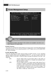
In this field. Set- tings are available only when your BIOS supports S3 sleep mode. MS-7508 Mainboard Power Management Setup Important S3-related functions described in this section are : [S1] The S1 sleep mode is a low power state. The information stored ...
In this field. Set- tings are available only when your BIOS supports S3 sleep mode. MS-7508 Mainboard Power Management Setup Important S3-related functions described in this section are : [S1] The S1 sleep mode is a low power state. The information stored ...

User Guide
Page 50
MS-7508 Mainboard Resume From S3 By PS/2 M ouse This setting determines whether the system will be awakened from what power saving modes when input signal of ...
MS-7508 Mainboard Resume From S3 By PS/2 M ouse This setting determines whether the system will be awakened from what power saving modes when input signal of ...


