
User Guide
Page 2
... for FAQ, technical guide, BIOS updates, driver updates, and other countries. Netware® is the intellectual property of Intel Corporation. Revision History Revision V1.0 V1.1 Revision History First release Add RAID appendix Date December 2006 April 2007 Technical Support If a problem arises with your system and no guarantee is given as to make changes without notice. AMD, Athlon™, Athlon...
... for FAQ, technical guide, BIOS updates, driver updates, and other countries. Netware® is the intellectual property of Intel Corporation. Revision History Revision V1.0 V1.1 Revision History First release Add RAID appendix Date December 2006 April 2007 Technical Support If a problem arises with your system and no guarantee is given as to make changes without notice. AMD, Athlon™, Athlon...

User Guide
Page 8
...1-1 Mainboard Specifications 1-2 Mainboard Layout 1-4 Packing Checklist 1-4 Setup audio output to HDMI port 1-6 Chapter 2. Hardware Setup 2-1 Quick Components Guide 2-2 CPU (Central Processing Unit 2-2 CPU Installation Procedures for Socket AM2 2-4 Installing AMD Socket AM2 CPU Cooler Set 2-5 Memory ...2-6 Memory Module Population Rules 2-6 Installing DDRII Modules 2-7 Power Supply ...2-8 ATX 24-Pin Power Connector: ATX1 2-8 ATX 12V Power Connector: JPW 1 2-8 Back Panel ...2-9 Connectors ...2-11 Floppy Disk Drive Connector: FDD1 2-11 ATA133 Hard Disk Connectors: IDE1 2-11 Serial...
...1-1 Mainboard Specifications 1-2 Mainboard Layout 1-4 Packing Checklist 1-4 Setup audio output to HDMI port 1-6 Chapter 2. Hardware Setup 2-1 Quick Components Guide 2-2 CPU (Central Processing Unit 2-2 CPU Installation Procedures for Socket AM2 2-4 Installing AMD Socket AM2 CPU Cooler Set 2-5 Memory ...2-6 Memory Module Population Rules 2-6 Installing DDRII Modules 2-7 Power Supply ...2-8 ATX 24-Pin Power Connector: ATX1 2-8 ATX 12V Power Connector: JPW 1 2-8 Back Panel ...2-9 Connectors ...2-11 Floppy Disk Drive Connector: FDD1 2-11 ATA133 Hard Disk Connectors: IDE1 2-11 Serial...

User Guide
Page 9
...Header: JSPI1 2-18 Jumpers ...2-18 Clear CMOS Jumper: JBAT1 2-19 Slots ...2-20 PCI (Peripheral Component Interconnect) Express Slots 2-20 PCI (Peripheral Component Interconnect) Slots 2-21 PCI Interrupt Request Routing 2-21 Chapter 3 BIOS Setup 3-1 Entering Setup ...3-2 The Main Menu ...3-4 Standard CMOS Features 3-6 Advanced BIOS Features 3-8 Advanced Chipset Features 3-10 Integrated Peripherals 3-12 Power Management Setup 3-14 PNP/PCI Configurations 3-18 H/W Monitor ...3-21 Load Optimized Defaults 3-22 BIOS Setting Password 3-22 Appendix A Realtek ALC888 Audio A-1 Installation...
...Header: JSPI1 2-18 Jumpers ...2-18 Clear CMOS Jumper: JBAT1 2-19 Slots ...2-20 PCI (Peripheral Component Interconnect) Express Slots 2-20 PCI (Peripheral Component Interconnect) Slots 2-21 PCI Interrupt Request Routing 2-21 Chapter 3 BIOS Setup 3-1 Entering Setup ...3-2 The Main Menu ...3-4 Standard CMOS Features 3-6 Advanced BIOS Features 3-8 Advanced Chipset Features 3-10 Integrated Peripherals 3-12 Power Management Setup 3-14 PNP/PCI Configurations 3-18 H/W Monitor ...3-21 Load Optimized Defaults 3-22 BIOS Setting Password 3-22 Appendix A Realtek ALC888 Audio A-1 Installation...
User Guide
Page 11
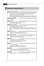
... devices by 8111B 1394 (Optional) - Supports 10/100/1000 Fast Ethernet by AMD® SB600 - Flexible 8-channel audio with Azalia 1.0 spec IDE - 1 IDE port by SB600 - Supports PIO, Bus Master operation mode SATA - Supports up to 400Mbps - MS-7327 Mainboard Mainboard Specifications Processor Support - Supports 4 pin CPU Fan Pin-Header with Fan Speed Control - Chip integrated by AMD® SB600 1-2 Supports 2 IEEE1394 ports, transfer rate is up to 300MB/s RAID - DDRII 800/667/533/400 DRAM (4GB Max) - 2 DDRII DIMMs (240pin / 1.8V) (For m ore information on compatible...
... devices by 8111B 1394 (Optional) - Supports 10/100/1000 Fast Ethernet by AMD® SB600 - Flexible 8-channel audio with Azalia 1.0 spec IDE - 1 IDE port by SB600 - Supports PIO, Bus Master operation mode SATA - Supports up to 400Mbps - MS-7327 Mainboard Mainboard Specifications Processor Support - Supports 4 pin CPU Fan Pin-Header with Fan Speed Control - Chip integrated by AMD® SB600 1-2 Supports 2 IEEE1394 ports, transfer rate is up to 300MB/s RAID - DDRII 800/667/533/400 DRAM (4GB Max) - 2 DDRII DIMMs (240pin / 1.8V) (For m ore information on compatible...
User Guide
Page 12
Micro-ATX (24.4cm X 21.5 cm) Mounting - 6 mounting holes 1-3 Supports 1 FDD with 360K, 720K, 1.2M, 1.44M and 2.88Mbytes Connectors Back panel - 1 PS/2 mouse port - 1 PS/2 keyboard port - 1 HDMI port (optional) - 1 VGA port - 1 parallel port supporting SPP/EPP/ECP mode - 4 USB 2.0 Ports - 1 LAN jack - 6 flexible audio jacks - 1 1394 port (optional) On-Board Pinheaders - 3 USB 2.0 pinheaders - 1 1394 pinheader (optional) - 1 TV-out pinheader (optional) - 1 Audio pinheader - 1 CD-in connector - 1 SPDIF out connector (optional) - 1 SPDIF in connector (optional) - 4 Serial ATA ports Slots - 1 PCI ...
Micro-ATX (24.4cm X 21.5 cm) Mounting - 6 mounting holes 1-3 Supports 1 FDD with 360K, 720K, 1.2M, 1.44M and 2.88Mbytes Connectors Back panel - 1 PS/2 mouse port - 1 PS/2 keyboard port - 1 HDMI port (optional) - 1 VGA port - 1 parallel port supporting SPP/EPP/ECP mode - 4 USB 2.0 Ports - 1 LAN jack - 6 flexible audio jacks - 1 1394 port (optional) On-Board Pinheaders - 3 USB 2.0 pinheaders - 1 1394 pinheader (optional) - 1 TV-out pinheader (optional) - 1 Audio pinheader - 1 CD-in connector - 1 SPDIF out connector (optional) - 1 SPDIF in connector (optional) - 4 Serial ATA ports Slots - 1 PCI ...
User Guide
Page 15
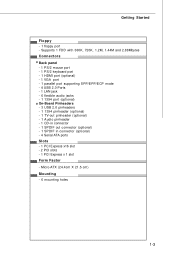
... Mainboard Setup audio output to install the driver. 4. Click Next to HDMI port Install ATI HDMI Audio Driver To install the ATI HDMI Audio driver follow these steps 1. Restart the computer after the driver installation procedure. Setup Sounds and Audio Devices Go to: Start -> Control Panel -> Sounds and Audio Devices W hen the ATI HDMI Audio Driver is correctly installed, there will automatically appear. 2. Click ATI HDMI Audio Driver. 3. Select the item and then click the OK button 1-6 The setup screen will be one device for the Realtek HDA HDMI...
... Mainboard Setup audio output to install the driver. 4. Click Next to HDMI port Install ATI HDMI Audio Driver To install the ATI HDMI Audio driver follow these steps 1. Restart the computer after the driver installation procedure. Setup Sounds and Audio Devices Go to: Start -> Control Panel -> Sounds and Audio Devices W hen the ATI HDMI Audio Driver is correctly installed, there will automatically appear. 2. Click ATI HDMI Audio Driver. 3. Select the item and then click the OK button 1-6 The setup screen will be one device for the Realtek HDA HDMI...

User Guide
Page 23
MS-7327 Mainboard Power Supply ATX 24-Pin Power Connector: ATX1 This connector allows you like to use the 20-pin ATX power supply as you to avoid wrong installation. Maker sure that all the connectors are aligned. To connect the ATX 24-pin power supply, make sure the plug of the mainboard. 2. Then push down the power supply firmly into the connector. Pin Definition 13 1 PIN SIGNAL PIN SIGNAL 1 +3.3V 13 +3.3V 2 +3.3V 14 -12V ATX1 3 GND 4 +5V...
MS-7327 Mainboard Power Supply ATX 24-Pin Power Connector: ATX1 This connector allows you like to use the 20-pin ATX power supply as you to avoid wrong installation. Maker sure that all the connectors are aligned. To connect the ATX 24-pin power supply, make sure the plug of the mainboard. 2. Then push down the power supply firmly into the connector. Pin Definition 13 1 PIN SIGNAL PIN SIGNAL 1 +3.3V 13 +3.3V 2 +3.3V 14 -12V ATX1 3 GND 4 +5V...
User Guide
Page 26
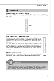
... connector supports 360K, 720K, 1.2M, 1.44M and 2.88M floppy disk types. Refer to 133 megabytes (MB) per second. You can connect a Master and a Slave drive. IDE1 Important If you install two hard disks on IDE cable, you must configure the second hard drive to Slave mode by hard disk vendors for jumper setting instructions. 2-11 FDD1 ATA133 Hard Disk Connectors: IDE1 The mainboard has a 32-bit Enhanced PCI IDE and Ultra DMA 66/100/133 controller that provides PIO mode 0~4, Bus...
... connector supports 360K, 720K, 1.2M, 1.44M and 2.88M floppy disk types. Refer to 133 megabytes (MB) per second. You can connect a Master and a Slave drive. IDE1 Important If you install two hard disks on IDE cable, you must configure the second hard drive to Slave mode by hard disk vendors for jumper setting instructions. 2-11 FDD1 ATA133 Hard Disk Connectors: IDE1 The mainboard has a 32-bit Enhanced PCI IDE and Ultra DMA 66/100/133 controller that provides PIO mode 0~4, Bus...
User Guide
Page 28
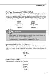
Chassis Intrusion Switch Connector: JCI1 This connector connects to the connectors, always take advantage of the CPU fan c on the screen. Hardware Setup Fan Power Connectors: CPUFAN1, SYSFAN1 The fan power connectors support system cooling fan with 3 or 4 pins are both available for CD-ROM audio. If the mainboard has a System Hardware Monitor chipset on-board, you must use a specially designed fan with speed sensor to take note that the red wire is the positive and should be connected to the...
Chassis Intrusion Switch Connector: JCI1 This connector connects to the connectors, always take advantage of the CPU fan c on the screen. Hardware Setup Fan Power Connectors: CPUFAN1, SYSFAN1 The fan power connectors support system cooling fan with 3 or 4 pins are both available for CD-ROM audio. If the mainboard has a System Hardware Monitor chipset on-board, you must use a specially designed fan with speed sensor to take note that the red wire is the positive and should be connected to the...
User Guide
Page 29
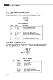
... Hard disk LED pull-up MSG LED pull-up Hard disk active LED MSG LED pull-up Reset Switch low reference pull-down to GND Power Switch high reference pull-up Reset Switch high reference pull-up Power Switch low reference pull-down to GND Reserved. Do not use to control headphone amplifier 8 KEY No pin 9 AUD_FPOUT_L Left channel audio signal to front panel 10 AUD_RET_L Left channel audio signal return from front panel 7 HP_ON Reserved for electrical connection...
... Hard disk LED pull-up MSG LED pull-up Hard disk active LED MSG LED pull-up Reset Switch low reference pull-down to GND Power Switch high reference pull-up Reset Switch high reference pull-up Power Switch low reference pull-down to GND Reserved. Do not use to control headphone amplifier 8 KEY No pin 9 AUD_FPOUT_L Left channel audio signal to front panel 10 AUD_RET_L Left channel audio signal return from front panel 7 HP_ON Reserved for electrical connection...
User Guide
Page 34
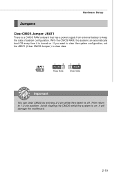
If you want to clear the system configuration, set the JBAT1 (Clear CMOS Jumper ) to 1-2 pin position. JBAT1 1 1 3 Keep Data 1 3 Clear Data Important You can automatically boot OS every time it will damage the mainboard. 2-19 it is on . Hardware Setup Jumpers Clear CMOS Jumper: JBAT1 There is off. With the CMOS RAM, the system can clear CMOS by shorting 2-3 pin while the system is a CMOS RAM onboard that has a power supply from external battery to keep the...
If you want to clear the system configuration, set the JBAT1 (Clear CMOS Jumper ) to 1-2 pin position. JBAT1 1 1 3 Keep Data 1 3 Clear Data Important You can automatically boot OS every time it will damage the mainboard. 2-19 it is on . Hardware Setup Jumpers Clear CMOS Jumper: JBAT1 There is off. With the CMOS RAM, the system can clear CMOS by shorting 2-3 pin while the system is a CMOS RAM onboard that has a power supply from external battery to keep the...

User Guide
Page 35
When adding or removing expansion cards, make sure that you unplug the power supply first. Also, desktop platforms with PCI Express Architecture will be designed to configure any necessary hardware or software settings for the ex pansion card, such as jumpers, switches or BIOS configuration. 2-20 PCI Express x1 Slot PCI Express x16 Slot Important 1. Meanwhile, read the documentation for graphics controllers, while PCI Express x1 supports transfer rate of 4.0 GB/s over a PCI Express x1 lane for Gigabit Ethernet...
When adding or removing expansion cards, make sure that you unplug the power supply first. Also, desktop platforms with PCI Express Architecture will be designed to configure any necessary hardware or software settings for the ex pansion card, such as jumpers, switches or BIOS configuration. 2-20 PCI Express x1 Slot PCI Express x16 Slot Important 1. Meanwhile, read the documentation for graphics controllers, while PCI Express x1 supports transfer rate of 4.0 GB/s over a PCI Express x1 lane for Gigabit Ethernet...
User Guide
Page 43
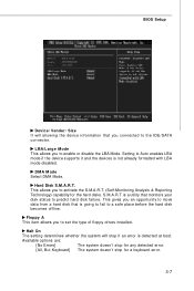
... hard disk failure. Setting to Auto enables LBA mode if the device supports it and the devices is a utility that monitors your disk status to activate the S.M.A.R.T. (Self-Monitoring Analysis & Reporting Technology) capability for a keyboard error. 3-7 LBA/Large M ode This allows you an opportunity to move data from a hard disk that you to the IDE/SATA connector. Halt On The setting determines whether the system will showing the device information that is detected at boot. Hard Disk S.M.A.R.T. BIOS Setup Device...
... hard disk failure. Setting to Auto enables LBA mode if the device supports it and the devices is a utility that monitors your disk status to activate the S.M.A.R.T. (Self-Monitoring Analysis & Reporting Technology) capability for a keyboard error. 3-7 LBA/Large M ode This allows you an opportunity to move data from a hard disk that you to the IDE/SATA connector. Halt On The setting determines whether the system will showing the device information that is detected at boot. Hard Disk S.M.A.R.T. BIOS Setup Device...
User Guide
Page 49
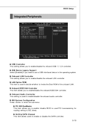
... disable BIOS to used PCI busmastering for reading/ writing to IDE drives. Onboard Audio Controller This setting is used to enable/disable the onboard audio controller. LAN Option ROM This item is used to decide whether to invoke the Boot ROM of the onboard LAN. OnChip SATA Channel This item allows users to enable/disable the onboard LAN controller. Onboard IEEE1394 Controller This item allows you to enable/disable the onboard USB 1.1/ 2.0 controller. Integrated Peripherals BIOS Setup USB Controller This setting allows you to enable/disable the onboard IEEE1394 controller. Onboard LAN...
... disable BIOS to used PCI busmastering for reading/ writing to IDE drives. Onboard Audio Controller This setting is used to enable/disable the onboard audio controller. LAN Option ROM This item is used to decide whether to invoke the Boot ROM of the onboard LAN. OnChip SATA Channel This item allows users to enable/disable the onboard LAN controller. Onboard IEEE1394 Controller This item allows you to enable/disable the onboard USB 1.1/ 2.0 controller. Integrated Peripherals BIOS Setup USB Controller This setting allows you to enable/disable the onboard IEEE1394 controller. Onboard LAN...
User Guide
Page 52
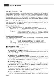
... an AGP driver to enter the sub-menu: Resume From S3 By USB Device The item allows the activity of the power button. Resume From S3 By PS/2 Keyboard This controls how the PS/2 keyboard is not detected for the length of the card does not support the initialization feature, the display may work abnormally or not function after a power failure or interrupt occurs. Specific Key PowerOn If...
... an AGP driver to enter the sub-menu: Resume From S3 By USB Device The item allows the activity of the power button. Resume From S3 By PS/2 Keyboard This controls how the PS/2 keyboard is not detected for the length of the card does not support the initialization feature, the display may work abnormally or not function after a power failure or interrupt occurs. Specific Key PowerOn If...
User Guide
Page 54
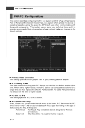
... IRQ will enter the sub-menu of device using the IRQ. PCI Latency Timer This item controls how long each IRQ a type depending on the type of the items. IRQ Resources list IRQ 3/4/5/7/9/10/11/12/14/15 for users to the default settings. IRQ Resources Setup Press and you should make any changes to set the item to higher values. Settings are: PCI Device For Plug & Play compatible devices designed for...
... IRQ will enter the sub-menu of device using the IRQ. PCI Latency Timer This item controls how long each IRQ a type depending on the type of the items. IRQ Resources list IRQ 3/4/5/7/9/10/11/12/14/15 for users to the default settings. IRQ Resources Setup Press and you should make any changes to set the item to higher values. Settings are: PCI Device For Plug & Play compatible devices designed for...
User Guide
Page 56
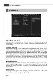
.... Chassis Intrusion The field enables or disables the feature of the field will remove (turn off) clocks from overheading due to [Enabled] later. But if you do not have any EMI problem, leave the setting at [Disabled] for EMI reduction. MS-7327 Mainboard H/W Monitor Auto Disable PCI Clock This item is once opened. To clear the warning message, set to [Enabled], the system will automatically return to the heavy working loading...
.... Chassis Intrusion The field enables or disables the feature of the field will remove (turn off) clocks from overheading due to [Enabled] later. But if you do not have any EMI problem, leave the setting at [Disabled] for EMI reduction. MS-7327 Mainboard H/W Monitor Auto Disable PCI Clock This item is once opened. To clear the warning message, set to [Enabled], the system will automatically return to the heavy working loading...
User Guide
Page 60
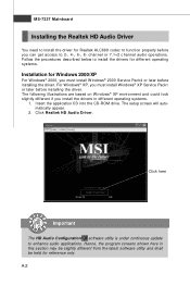
... CD-ROM drive. For Windows® XP, you install the drivers in this section may be slightly different from the latest software utility and shall be held for reference only. channel or 7.1+2 channel audio operations. Click Realtek HD Audio Driver. MS-7327 Mainboard Installing the Realtek HD Audio Driver You need to install the driver for Realtek ALC888 codec to function properly before you must install W indows® XP Service...
... CD-ROM drive. For Windows® XP, you install the drivers in this section may be slightly different from the latest software utility and shall be held for reference only. channel or 7.1+2 channel audio operations. Click Realtek HD Audio Driver. MS-7327 Mainboard Installing the Realtek HD Audio Driver You need to install the driver for Realtek ALC888 codec to function properly before you must install W indows® XP Service...
User Guide
Page 88
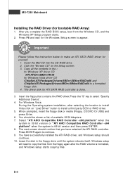
... RAID volume is formatted, and W indows setup starts copying files. Insert the floppy that you complete the RAID BIOS setup, boot from the floppy again after selecting the location to a formatted floppy disk. 4. You should continue. 10. The next screen should confirm that contains the RAID driver,Press the "S" key to make an ATI SATA RAID driver for yourself. 1. Important Please follow the instruction below to select "Specify Additional Device". 4. Select "ATI AHCI Compatible RAID Controller...
... RAID volume is formatted, and W indows setup starts copying files. Insert the floppy that you complete the RAID BIOS setup, boot from the floppy again after selecting the location to a formatted floppy disk. 4. You should continue. 10. The next screen should confirm that contains the RAID driver,Press the "S" key to make an ATI SATA RAID driver for yourself. 1. Important Please follow the instruction below to select "Specify Additional Device". 4. Select "ATI AHCI Compatible RAID Controller...

User Guide
Page 89
Insert the MSI CD into the CD-ROM drive. 2. The driver will appear. 3. ATi SATA RAID Installing the RAID Driver Under Windows (for Non-bootable RAID Array) 1. B-9 Under the Driver tab, click on ATI System Driver. The ATI System Driver includes ATI RAID Driver. 4. The CD will auto-run and the setup screen will be automatically installed. Important You must install the RAID driver to enable RAID.
Insert the MSI CD into the CD-ROM drive. 2. The driver will appear. 3. ATi SATA RAID Installing the RAID Driver Under Windows (for Non-bootable RAID Array) 1. B-9 Under the Driver tab, click on ATI System Driver. The ATI System Driver includes ATI RAID Driver. 4. The CD will auto-run and the setup screen will be automatically installed. Important You must install the RAID driver to enable RAID.


