
User Guide
Page 8
... Unit 2-4 Power Supply ...2-6 Back Panel ...2-7 Connector ...2-9 Jumper ...2-16 Slot ...2-17 Chapter 3 BIOS Setup 3-1 Entering Setup ...3-2 The Menu Bar ...3-4 Main ...3-5 Advanc ed ...3-6 Boot ...3-19 Security ...3-21 Chipset ...3-22 Exit ...3-26 Chapter 4 System Resources 4-1 Watch Dog Timer Setting 4-2 AMI POST Code 4-3 Resource List ...4-7 viii
... Unit 2-4 Power Supply ...2-6 Back Panel ...2-7 Connector ...2-9 Jumper ...2-16 Slot ...2-17 Chapter 3 BIOS Setup 3-1 Entering Setup ...3-2 The Menu Bar ...3-4 Main ...3-5 Advanc ed ...3-6 Boot ...3-19 Security ...3-21 Chipset ...3-22 Exit ...3-26 Chapter 4 System Resources 4-1 Watch Dog Timer Setting 4-2 AMI POST Code 4-3 Resource List ...4-7 viii
User Guide
Page 10
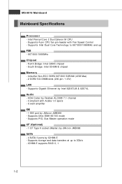
... Dual Core Technology to 3Gb/s - North Bridge: Intel GM45 chipset - Unbuffer Non-ECC DDR2 667/800 SDRAM (4GB Max) - 2 DDR2 SO-DIMM slots (200-pin / 1.8V) LAN - Supports storage and data transfers at up to 667/800/1066MHz and up FSB - 667/800/1066MHz Chipset - Supports Gigabit Ethernet by Realtek ALC888 7.1 channel - Intel... II ports by JMicron JMB368 - Supports 4-pin CPU fan pin-header with Azalia 1.0 specs - 6 watt amplifier IDE - 1 IDE port by ICH9M-E - South Bridge: Intel ICH9M-E chipset M emor y - Compliant with Fan Speed Control -
... Dual Core Technology to 3Gb/s - North Bridge: Intel GM45 chipset - Unbuffer Non-ECC DDR2 667/800 SDRAM (4GB Max) - 2 DDR2 SO-DIMM slots (200-pin / 1.8V) LAN - Supports storage and data transfers at up to 667/800/1066MHz and up FSB - 667/800/1066MHz Chipset - Supports Gigabit Ethernet by Realtek ALC888 7.1 channel - Intel... II ports by JMicron JMB368 - Supports 4-pin CPU fan pin-header with Azalia 1.0 specs - 6 watt amplifier IDE - 1 IDE port by ICH9M-E - South Bridge: Intel ICH9M-E chipset M emor y - Compliant with Fan Speed Control -
User Guide
Page 30
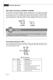
... to GND. Front Panel Connector: JFP1 The mainboard provides one front panel connector for proper CPU cooling fan. If the mainboard has a System Hardware Monitor chipset onboard, you must use . 2-12 MS-9818 Mainboard Fan Power Connectors: CPUFAN1, SYSFAN1 The fan power connectors support system cooling fan with Intel® Front...
... to GND. Front Panel Connector: JFP1 The mainboard provides one front panel connector for proper CPU cooling fan. If the mainboard has a System Hardware Monitor chipset onboard, you must use . 2-12 MS-9818 Mainboard Fan Power Connectors: CPUFAN1, SYSFAN1 The fan power connectors support system cooling fan with Intel® Front...

User Guide
Page 38
... where: 1st digit refers to BIOS maker as A = AMI, W = AWARD, and P = PHOENIX. 2nd - 5th digit refers to the model number. 6th digit refers to the chipset as I = Intel, N = nVidia, and V = VIA. 7th - 8th digit refers to the customer as MS = all standard customers. You may be slightly different from the latest...
... where: 1st digit refers to BIOS maker as A = AMI, W = AWARD, and P = PHOENIX. 2nd - 5th digit refers to the model number. 6th digit refers to the chipset as I = Intel, N = nVidia, and V = VIA. 7th - 8th digit refers to the customer as MS = all standard customers. You may be slightly different from the latest...

User Guide
Page 40
Chipset This menu controls the advanced features of boot devices. Security Use this menu to set up the items of special enhanced features. MS-9818 Mainboard The Menu Bar Main Use this menu to load the BIOS default values or factory default settings into the BIOS and exit the BIOS setup utility with or without changes. 3-4 Boot Use this menu to specify the priority of the onboard Northbridge and Southbridge. Exit This menu allows you to set supervisor and user passwords. Ad v a nc e d Use this menu for basic system configurations, such as time, date etc.
Chipset This menu controls the advanced features of boot devices. Security Use this menu to set up the items of special enhanced features. MS-9818 Mainboard The Menu Bar Main Use this menu to load the BIOS default values or factory default settings into the BIOS and exit the BIOS setup utility with or without changes. 3-4 Boot Use this menu to specify the priority of the onboard Northbridge and Southbridge. Exit This menu allows you to set supervisor and user passwords. Ad v a nc e d Use this menu for basic system configurations, such as time, date etc.