
User Guide
Page 18
To clear the warning, you must enter the BIOS utility and clear the record. 1.C2.IGNTroRuUnd APS LED Status Indicator: LED1 These APS (Active Phase Switching) LED indicates the current CPU power phase mode. ...
To clear the warning, you must enter the BIOS utility and clear the record. 1.C2.IGNTroRuUnd APS LED Status Indicator: LED1 These APS (Active Phase Switching) LED indicates the current CPU power phase mode. ...

User Guide
Page 20
... removing expansion cards, make the IRQ, acronym of interrupt request line and pronounced I-R-Q, are typically connected to the PCI bus pins as jumpers, switches or BIOS configuration. Important Make sure that comply with PCI specifications. PCI Express Slot The PCI Express slot supports the PCI Express interface expansion card. The PCI...
... removing expansion cards, make the IRQ, acronym of interrupt request line and pronounced I-R-Q, are typically connected to the PCI bus pins as jumpers, switches or BIOS configuration. Important Make sure that comply with PCI specifications. PCI Express Slot The PCI Express slot supports the PCI Express interface expansion card. The PCI...
User Guide
Page 21
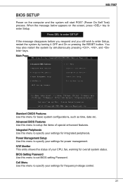
... This entry shows the status of special enhanced features. Power Management Setup Use this menu to set BIOS setting Password. Advanced BIOS Features Use this menu to specify your settings for frequency/voltage control. 21 BIOS Setting Password Use this menu to enter Setup. When the message below appears on the computer and... system by simultaneously pressing , , and keys. You may also restart the system by turning it OFF and On or pressing the RESET button. MS-7597 BIOS Setup Power on the screen, press key to specify your settings for integrated peripherals.
... This entry shows the status of special enhanced features. Power Management Setup Use this menu to set BIOS setting Password. Advanced BIOS Features Use this menu to specify your settings for frequency/voltage control. 21 BIOS Setting Password Use this menu to enter Setup. When the message below appears on the computer and... system by simultaneously pressing , , and keys. You may also restart the system by turning it OFF and On or pressing the RESET button. MS-7597 BIOS Setup Power on the screen, press key to specify your settings for integrated peripherals.
User Guide
Page 22
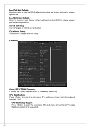
.... CPU Specifications Press to enter the sub-menu. CPU Technology Support Press to enter the sub-menu. Save & Exit Setup Save changes to load the BIOS default values that the installed CPU supported. 22 Exit Without Saving Abandon all changes and exit setup. Read-only. This sub-menu shows the technologies... system performance operations. This submenu shows the information of CPU/ Memory. Load Fail-Safe Defaults Use this menu to load factory default settings into the BIOS for system operations. Load Optimized Defaults Use this menu to CMOS and exit setup.
.... CPU Specifications Press to enter the sub-menu. CPU Technology Support Press to enter the sub-menu. Save & Exit Setup Save changes to load the BIOS default values that the installed CPU supported. 22 Exit Without Saving Abandon all changes and exit setup. Read-only. This sub-menu shows the technologies... system performance operations. This submenu shows the information of CPU/ Memory. Load Fail-Safe Defaults Use this menu to load factory default settings into the BIOS for system operations. Load Optimized Defaults Use this menu to CMOS and exit setup.
User Guide
Page 23
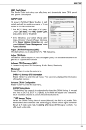
Important To ensure that : * Run BIOS Setup, and select Cell Menu. Under Cell Menu, find AMD Cool'n'Quiet, and set this field to [DCT 0], [DCT 1] or [Both], some fields will be ...
Important To ensure that : * Run BIOS Setup, and select Cell Menu. Under Cell Menu, find AMD Cool'n'Quiet, and set this field to [DCT 0], [DCT 1] or [Both], some fields will be ...

User Guide
Page 36
전면 USB 커넥터: JUSB1/ JUSB2 Intel® I/O Connectivity Design Guide USB HDD MP3 USB TPM JTPM1 (옵션) TPM(Trusted Platform Module 용법은 TPM 2.34V.36S..3tS8aVe.n15Prd0iVaob1.NlwyP2I1o.eRopG4rwoPQ.rwGeionreurornudnd 1.L3P.L5CP.LCC7P.loLRC9cP.eLka1CsPd1e1ad.CtL3drPea.dLsdCrPsedasCr&edsFdsd&sraraedt&amsasdpteaa&intpa0dinap1tian2pin3 JCI1 BIOS 1.C2.IGNTroRuUnd APS LED LED1 이 APS (Active Phase Switching) LED는 현재 CPU LED1 CPU가 3 LED CPU가 1 LED 36
전면 USB 커넥터: JUSB1/ JUSB2 Intel® I/O Connectivity Design Guide USB HDD MP3 USB TPM JTPM1 (옵션) TPM(Trusted Platform Module 용법은 TPM 2.34V.36S..3tS8aVe.n15Prd0iVaob1.NlwyP2I1o.eRopG4rwoPQ.rwGeionreurornudnd 1.L3P.L5CP.LCC7P.loLRC9cP.eLka1CsPd1e1ad.CtL3drPea.dLsdCrPsedasCr&edsFdsd&sraraedt&amsasdpteaa&intpa0dinap1tian2pin3 JCI1 BIOS 1.C2.IGNTroRuUnd APS LED LED1 이 APS (Active Phase Switching) LED는 현재 CPU LED1 CPU가 3 LED CPU가 1 LED 36

User Guide
Page 40
Load Fail-Safe Defaults BIOS Load Optimized Defaults BIOS Save & Exit Setup CMOS Exit Without Saving Cell Menu Current CPU/ DRAM Frequency (현재 CPU / DRAM 주파수) CPU CPU Specifications (CPU 사양)
Load Fail-Safe Defaults BIOS Load Optimized Defaults BIOS Save & Exit Setup CMOS Exit Without Saving Cell Menu Current CPU/ DRAM Frequency (현재 CPU / DRAM 주파수) CPU CPU Specifications (CPU 사양)

User Guide
Page 108
...;) TPM (Trusted Platform Module TPM 2.34V.36S..3tS8aVe.n15Prd0iVaob1.NlwyP2I1o.eRopG4rwoPQ.rwGeionreurornudnd 1.L3P.L5CP.LCC7P.loLRC9cP.eLka1CsPd1e1ad.CtL3drPea.dLsdCrPsedasCr&edsFdsd&sraraedt&amsasdpteaa&intpa0dinap1tian2pin3 JCI1 BIOS 1.C2.IGNTroRuUnd APS LED LED1 这些 APS (Active Phase Switching CPU LED1 开 当 CPU 处于 3 LED 灯亮。 关 当 CPU...
...;) TPM (Trusted Platform Module TPM 2.34V.36S..3tS8aVe.n15Prd0iVaob1.NlwyP2I1o.eRopG4rwoPQ.rwGeionreurornudnd 1.L3P.L5CP.LCC7P.loLRC9cP.eLka1CsPd1e1ad.CtL3drPea.dLsdCrPsedasCr&edsFdsd&sraraedt&amsasdpteaa&intpa0dinap1tian2pin3 JCI1 BIOS 1.C2.IGNTroRuUnd APS LED LED1 这些 APS (Active Phase Switching CPU LED1 开 当 CPU 处于 3 LED 灯亮。 关 当 CPU...

User Guide
Page 110
PCI Express 插槽 此PCI Express PCI The PCI Express 1.0 x16 插槽 The PCI Express 1.0 x1 插槽 PCI 插槽 此PCI SCSI卡,USB PCI BIOS配置。 PCI IRQ PCI的IRQ PCI 顺序 1 2 3 4 插槽 PCI 1 C# D# A# B# PCI 2 B# C# D# A# 110
PCI Express 插槽 此PCI Express PCI The PCI Express 1.0 x16 插槽 The PCI Express 1.0 x1 插槽 PCI 插槽 此PCI SCSI卡,USB PCI BIOS配置。 PCI IRQ PCI的IRQ PCI 顺序 1 2 3 4 插槽 PCI 1 C# D# A# B# PCI 2 B# C# D# A# 110

User Guide
Page 112
Cell Menu Load Fail-Safe Defaults BIOS Load Optimized Defaults BIOS值。 Save & Exit Setup CMOS Setup程序。 Exit Without Saving CMOS Setup Current CPU/DRAM Frequency(当前 CPU CPU CPU Specifications(CPU Enter CPU信息。 CPU Technology Support(CPU Enter CPU 112
Cell Menu Load Fail-Safe Defaults BIOS Load Optimized Defaults BIOS值。 Save & Exit Setup CMOS Setup程序。 Exit Without Saving CMOS Setup Current CPU/DRAM Frequency(当前 CPU CPU CPU Specifications(CPU Enter CPU信息。 CPU Technology Support(CPU Enter CPU 112

User Guide
Page 130
Cell Menu Load Fail-Safe Defaults BIOS Load Optimized Defaults BIOS Save & Exit Setup CMOS Exit Without Saving Cell Menu Current CPU/ DRAM Frequency (目前 CPU CPU CPU Specifications (CPU Enter CPU 訊息。 CPU Technology Support (CPU Enter CPU 130
Cell Menu Load Fail-Safe Defaults BIOS Load Optimized Defaults BIOS Save & Exit Setup CMOS Exit Without Saving Cell Menu Current CPU/ DRAM Frequency (目前 CPU CPU CPU Specifications (CPU Enter CPU 訊息。 CPU Technology Support (CPU Enter CPU 130
User Guide
Page 147
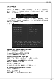
MS-7597 BIOSの設定 POST (Power On Self Test DEL Press DEL to enter SETUP (とと
MS-7597 BIOSの設定 POST (Power On Self Test DEL Press DEL to enter SETUP (とと

User Guide
Page 148
Load Fail-Safe Defaults BIOS Load Optimized Defaults BIOS Save & Exit Setup CMOS Exit Without Saving CMOS Current CPU/ DRAM Frequency(目下のCPU/ DRAM CPU CPU Specifications(CPUの仕様)
Load Fail-Safe Defaults BIOS Load Optimized Defaults BIOS Save & Exit Setup CMOS Exit Without Saving CMOS Current CPU/ DRAM Frequency(目下のCPU/ DRAM CPU CPU Specifications(CPUの仕様)

User Guide
Page 152
Load Optimized Defaults BIOS 152
Load Optimized Defaults BIOS 152


