User Guide
Page 1
... cause harmful interference to radio communications. n Increase the separation between the equipment and receiver. power cord, if any, must be determined by the party responsible for compliance could void the user's authority to operate the equipment. Micro-Star International MS-7529 G52-75291X1 n Connect the equipment into an outlet on , the user...
... cause harmful interference to radio communications. n Increase the separation between the equipment and receiver. power cord, if any, must be determined by the party responsible for compliance could void the user's authority to operate the equipment. Micro-Star International MS-7529 G52-75291X1 n Connect the equipment into an outlet on , the user...
User Guide
Page 3
... not leave this equipment away from overheating. n Make sure the voltage of the following situations arises, get it . n Always Unplug the Power Cord before inserting any liquid into the equipment. - The equipment does not work well or you can not step on it work according to.... Liquid has penetrated into the opening that people can not get the equipment checked by the manufacturer. The equipment has been exposed to the power inlet. n Never pour any add-on a reliable flat surface before connecting the equipment to moisture. - CAUTION: Danger of breakage. n ...
... not leave this equipment away from overheating. n Make sure the voltage of the following situations arises, get it . n Always Unplug the Power Cord before inserting any liquid into the equipment. - The equipment does not work well or you can not step on it work according to.... Liquid has penetrated into the opening that people can not get the equipment checked by the manufacturer. The equipment has been exposed to the power inlet. n Never pour any add-on a reliable flat surface before connecting the equipment to moisture. - CAUTION: Danger of breakage. n ...
User Guide
Page 8
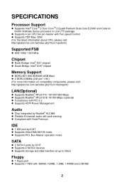
...DDR2 667/ 800 SDRAM (4GB Max) l 2 DDR2 DIMMs (240 pin/ 1.8V) (For more information on compatible components, please visit: http://global.msi.com.tw/index.php?func=testreport) LAN(Optional) l Supports Realtek® RTL8111C 10/100/1000 Mbps l Supports Realtek® RTL8101E 10/100 Mbps (...optional) l Compliance with PCI 2.2 l Supports ACPI Power Management Audio l Chip integrated by Realtek® ALC888 l Flexible 8-channel audio with jack sensing l Compliant with Vista Premium IDE l 1 IDE port by ...
...DDR2 667/ 800 SDRAM (4GB Max) l 2 DDR2 DIMMs (240 pin/ 1.8V) (For more information on compatible components, please visit: http://global.msi.com.tw/index.php?func=testreport) LAN(Optional) l Supports Realtek® RTL8111C 10/100/1000 Mbps l Supports Realtek® RTL8101E 10/100 Mbps (...optional) l Compliance with PCI 2.2 l Supports ACPI Power Management Audio l Chip integrated by Realtek® ALC888 l Flexible 8-channel audio with jack sensing l Compliant with Vista Premium IDE l 1 IDE port by ...
User Guide
Page 12
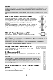
...disk drives, optical disk drives and other IDE devices. Each connector can connect to connect an ATX 24-pin power supply. ATX 24-Pin Power Connector: ATX1 This connector allows you like . ATX 12V power connection should always install DDR2 memory modules in the proper orientation and the pins are connected ... is inserted in the DDR2 DIMM slots. Refer to master / slave mode by the vendors for system stability. To connect the ATX 24-pin power supply, make sure the plug of the mainboard. Serial ATA Connector: SATA1 /SATA2/ SATA3/ SATA4 This connector is highly recommended for ...
...disk drives, optical disk drives and other IDE devices. Each connector can connect to connect an ATX 24-pin power supply. ATX 24-Pin Power Connector: ATX1 This connector allows you like . ATX 12V power connection should always install DDR2 memory modules in the proper orientation and the pins are connected ... is inserted in the DDR2 DIMM slots. Refer to master / slave mode by the vendors for system stability. To connect the ATX 24-pin power supply, make sure the plug of the mainboard. Serial ATA Connector: SATA1 /SATA2/ SATA3/ SATA4 This connector is highly recommended for ...
User Guide
Page 13
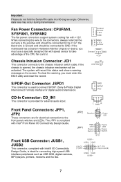
... CINTRU 1 S/PDIF-Out Connector: JSPD1 This connector is used to take advantage of the CPU fan control. Fan Power Connectors: CPUFAN1, SYSFAN1, SYSFAN2 The fan power connectors support system cooling fan with speed sensor to connect S/PDIF (Sony & Philips Digital Interconnect Format) interface for ... always note that the red wire is provided for digital audio transmission. L GND R JFP2 87 Speaker Power LED 21 JFP1 12 + -- + -+ HDD LED Power LED Reset Switch Power Switch 9 10 USB1+ USB1- If the mainboard has a System Hardware Monitor chipset on the screen. The...
... CINTRU 1 S/PDIF-Out Connector: JSPD1 This connector is used to take advantage of the CPU fan control. Fan Power Connectors: CPUFAN1, SYSFAN1, SYSFAN2 The fan power connectors support system cooling fan with speed sensor to connect S/PDIF (Sony & Philips Digital Interconnect Format) interface for ... always note that the red wire is provided for digital audio transmission. L GND R JFP2 87 Speaker Power LED 21 JFP1 12 + -- + -+ HDD LED Power LED Reset Switch Power Switch 9 10 USB1+ USB1- If the mainboard has a System Hardware Monitor chipset on the screen. The...
User Guide
Page 14
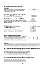
... on . PCI (Peripheral Component Interconnect) Slot 8 Please refer to 1-2 pin position. Serial Port Connector: JCOM1 This connector is a 16550A high speed communication port that has a power supply 1 from an external battery to keep the data of system 2 configuration. TPM Module connector: JTPM1(Optional) This connector connects to clear data. 1 2 3 Keep Data...
... on . PCI (Peripheral Component Interconnect) Slot 8 Please refer to 1-2 pin position. Serial Port Connector: JCOM1 This connector is a 16550A high speed communication port that has a power supply 1 from an external battery to keep the data of system 2 configuration. TPM Module connector: JTPM1(Optional) This connector connects to clear data. 1 2 3 Keep Data...
User Guide
Page 15
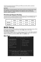
... as follows: PCI Slot1 PCI Slot2 Order1 INT A# INT B# Order2 INT B# INT C# Order3 INT C# INT D# Order4 INT D# INT A# BIOS Setup Power on the computer and the system will start POST (Power On Self Test) process. When the message below appears on cards that you still wish to the microprocessor. The PCI slot... expansion cards, make sure that comply with PCI specifications. Press DEL to enter SETUP If the message disappears before you respond and you unplug the power supply first.
... as follows: PCI Slot1 PCI Slot2 Order1 INT A# INT B# Order2 INT B# INT C# Order3 INT C# INT D# Order4 INT D# INT A# BIOS Setup Power on the computer and the system will start POST (Power On Self Test) process. When the message below appears on cards that you still wish to the microprocessor. The PCI slot... expansion cards, make sure that comply with PCI specifications. Press DEL to enter SETUP If the message disappears before you respond and you unplug the power supply first.
User Guide
Page 16
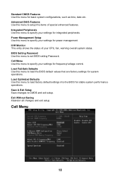
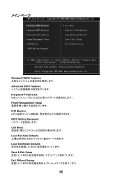
... changes and exit setup. Advanced BIOS Features Use this menu to set BIOS setting Password. Integrated Peripherals Use this menu to specify your settings for power management. Power Management Setup Use this menu to specify your CPU, fan, warning overall system status. Load Optimized Defaults Use this menu to load factory default...
... changes and exit setup. Advanced BIOS Features Use this menu to set BIOS setting Password. Integrated Peripherals Use this menu to specify your settings for power management. Power Management Setup Use this menu to specify your CPU, fan, warning overall system status. Load Optimized Defaults Use this menu to load factory default...
User Guide
Page 17
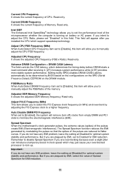
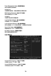
... the configurations on the SPD (Serial Presence Detect) EEPROM on battery or AC power. Adjusted DDR Memory Frequency It shows the adjusted DDR Memory frequency. Current CPU Frequency It shows the current frequency of Memory. Spread Spectrum When the motherboard's clock generator pulses, the extreme values (spikes) of the microprocessor whether the...
... the configurations on the SPD (Serial Presence Detect) EEPROM on battery or AC power. Adjusted DDR Memory Frequency It shows the adjusted DDR Memory frequency. Current CPU Frequency It shows the current frequency of Memory. Spread Spectrum When the motherboard's clock generator pulses, the extreme values (spikes) of the microprocessor whether the...
User Guide
Page 65
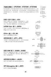
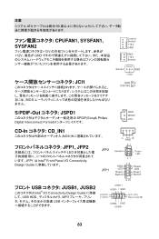
... 1 GND SPDIF VCC CD-In 接口: CD_IN1 CD-ROM JFP1, JFP2 JFP2 是和 Intel 的 I/O L GND R 87 JFP2 JFP1 Speaker Power LED 21 12 + -- + -+ HDD LED Power LED Reset Switch Power Switch 9 10 前置 USB 接口: JUSB1, JUSB2 Intel® I/O USB USB MP3 JAUD1 Intel®的 I/O USB1+ USB1-
... 1 GND SPDIF VCC CD-In 接口: CD_IN1 CD-ROM JFP1, JFP2 JFP2 是和 Intel 的 I/O L GND R 87 JFP2 JFP1 Speaker Power LED 21 12 + -- + -+ HDD LED Power LED Reset Switch Power Switch 9 10 前置 USB 接口: JUSB1, JUSB2 Intel® I/O USB USB MP3 JAUD1 Intel®的 I/O USB1+ USB1-
User Guide
Page 77
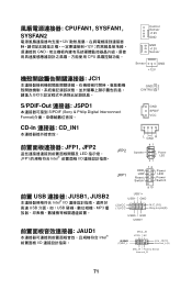
GND (2)VCC (1 )VC C N.C.(10) Key,no pin(9) USB0- GND USB0+ JAUD1 Intel I /O USB USB MP3 L GND R JFP2 87 Speaker Power LED 21 JFP1 12 + -- + -+ HDD LED Power LED Reset Switch Power Switch 9 10 USB1+ USB1- CPUFAN1, SYSFAN1, SYSFAN2 12V 12V GND CPU JCI1 BIOS Control Sensor +12V GND GND +12V Sensor Sensor GND +12V...
GND (2)VCC (1 )VC C N.C.(10) Key,no pin(9) USB0- GND USB0+ JAUD1 Intel I /O USB USB MP3 L GND R JFP2 87 Speaker Power LED 21 JFP1 12 + -- + -+ HDD LED Power LED Reset Switch Power Switch 9 10 USB1+ USB1- CPUFAN1, SYSFAN1, SYSFAN2 12V 12V GND CPU JCI1 BIOS Control Sensor +12V GND GND +12V Sensor Sensor GND +12V...
User Guide
Page 80
Power Management Setup H/W Monitor BIOS Setting Password(設定 BIOS BIOS 密碼。 Cell Menu Load Fail-Safe Defaults BIOS Load Optimized Defaults BIOS Save & Exit Setup CMOS Exit Without Saving Cell Menu Current CPU Frequency(目前 CPU CPU Current DRAM Frequency(目前 CPU DRAM 74
Power Management Setup H/W Monitor BIOS Setting Password(設定 BIOS BIOS 密碼。 Cell Menu Load Fail-Safe Defaults BIOS Load Optimized Defaults BIOS Save & Exit Setup CMOS Exit Without Saving Cell Menu Current CPU Frequency(目前 CPU CPU Current DRAM Frequency(目前 CPU DRAM 74
User Guide
Page 89
... VCC CD-In CD_IN1 L GND R JFP1, JFP2 LED JFP1 は Intel® Front Panel I/O Connectivity Design Guide JFP2 JFP1 87 Speaker Power LED 21 12 + -- + -+ HDD LED Power LED Reset Switch Power Switch 9 10 USB JUSB1, JUSB2 Intel® I/O Connectivity Design Guide に準拠 して、USB HDD MP3 USB USB1...
... VCC CD-In CD_IN1 L GND R JFP1, JFP2 LED JFP1 は Intel® Front Panel I/O Connectivity Design Guide JFP2 JFP1 87 Speaker Power LED 21 12 + -- + -+ HDD LED Power LED Reset Switch Power Switch 9 10 USB JUSB1, JUSB2 Intel® I/O Connectivity Design Guide に準拠 して、USB HDD MP3 USB USB1...
User Guide
Page 92
Standard CMOS Features Advanced BIOS Features Integrated Peripherals IDE I/O Power Management Setup H/W Monitor CPU BIOS Setting Password Cell Menu Load Fail-Safe Defaults BIOS Load Optimized Defaults BIOS Save & Exit Setup CMOS Exit Without Saving CMOS 86
Standard CMOS Features Advanced BIOS Features Integrated Peripherals IDE I/O Power Management Setup H/W Monitor CPU BIOS Setting Password Cell Menu Load Fail-Safe Defaults BIOS Load Optimized Defaults BIOS Save & Exit Setup CMOS Exit Without Saving CMOS 86

