
User Guide
Page 8
... Frequency Interference Statement iv W EEE (Waste Electrical and Electronic Equipment) Statement v Chapter 1. Hardware Setup 2-1 Quick Components Guide 2-2 CPU (Central Processing Unit 2-3 Memory ...2-7 Power Supply ...2-9 Back Panel ...2-10 Connectors ...2-12 Jumpers ...2-19 Slots ...2-20 Chapter 3 BIOS Setup 3-1 Entering Setup ...3-2 The Main Menu ...3-4 Standard CMOS Features 3-6 Advanced BIOS Features 3-9 Integrated Peripherals 3-12 Power...
... Frequency Interference Statement iv W EEE (Waste Electrical and Electronic Equipment) Statement v Chapter 1. Hardware Setup 2-1 Quick Components Guide 2-2 CPU (Central Processing Unit 2-3 Memory ...2-7 Power Supply ...2-9 Back Panel ...2-10 Connectors ...2-12 Jumpers ...2-19 Slots ...2-20 Chapter 3 BIOS Setup 3-1 Entering Setup ...3-2 The Main Menu ...3-4 Standard CMOS Features 3-6 Advanced BIOS Features 3-9 Integrated Peripherals 3-12 Power...

User Guide
Page 11
... with jack sensing To reach the 8-channel sound effect, the 7th and 8th channels must to 300MB/s - Transfer rate is up to output from front panel (pinheader) if you purchase the mainboard with 3 audio jacks. Supports PIO, Bus Master operation mode SATA - Supports four SATA II devices - Chip integrated by ICH7...
... with jack sensing To reach the 8-channel sound effect, the 7th and 8th channels must to 300MB/s - Transfer rate is up to output from front panel (pinheader) if you purchase the mainboard with 3 audio jacks. Supports PIO, Bus Master operation mode SATA - Supports four SATA II devices - Chip integrated by ICH7...

User Guide
Page 12
Support 3.3V/ 5V PCI bus Interface Form Factor - Micro-ATX (24.4cm X 21.8cm) Mounting - 6 mounting holes 1-3 Supports 1 FDD with 360KB, 720KB, 1.2MB, 1.44MB and 2.88MB Connectors Back panel - 1 PS/2 m ouse port - 1 PS/2 keyboard port - 1 serial port (COM1) - 1 VGA port - ...jacks (optional) On-Board Pinheaders/ Connectors - 2 USB 2.0 pinheaders - 1 CD-in pinheader - 1 SPDIF-Out pinheader - 1 IEEE 1394 pinheader (optional) - 1 Front Panel Audio pinheader - 1 serial port pinheader - 1 TPM (optional) - 1 Chassis Intrusion Switch pinheader Slots - 1 PCI Express x16 slot - 1 PCI Express x 1 slot...
Support 3.3V/ 5V PCI bus Interface Form Factor - Micro-ATX (24.4cm X 21.8cm) Mounting - 6 mounting holes 1-3 Supports 1 FDD with 360KB, 720KB, 1.2MB, 1.44MB and 2.88MB Connectors Back panel - 1 PS/2 m ouse port - 1 PS/2 keyboard port - 1 serial port (COM1) - 1 VGA port - ...jacks (optional) On-Board Pinheaders/ Connectors - 2 USB 2.0 pinheaders - 1 CD-in pinheader - 1 SPDIF-Out pinheader - 1 IEEE 1394 pinheader (optional) - 1 Front Panel Audio pinheader - 1 serial port pinheader - 1 TPM (optional) - 1 Chassis Intrusion Switch pinheader Slots - 1 PCI Express x16 slot - 1 PCI Express x 1 slot...
User Guide
Page 24
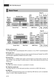
... a PS/2® mouse/keyboard. Serial Port The serial port is for monitor. 1394 Port (optional) The IEEE1394 port on the back panel provides connection to the connector. MS-7528 Mainboard Back Panel Mouse Keyboard Parallel Port 1394 Port (optional) Type A L-In RS-Out LAN L-Out CS-Out Serial Port VGA Port Mouse...
... a PS/2® mouse/keyboard. Serial Port The serial port is for monitor. 1394 Port (optional) The IEEE1394 port on the back panel provides connection to the connector. MS-7528 Mainboard Back Panel Mouse Keyboard Parallel Port 1394 Port (optional) Type A L-In RS-Out LAN L-Out CS-Out Serial Port VGA Port Mouse...

User Guide
Page 25
... are used for external CD player, tapeplayer or other audio devices. Line-In / RS-Out (Blue) - You can connect a network cable to output from front panel (pinheader) if you purchase the mainboard with another computer on the LAN. Activity Indicator Link Indicator LED Color Left Orange Green Right Orange LED State...
... are used for external CD player, tapeplayer or other audio devices. Line-In / RS-Out (Blue) - You can connect a network cable to output from front panel (pinheader) if you purchase the mainboard with another computer on the LAN. Activity Indicator Link Indicator LED Color Left Orange Green Right Orange LED State...

User Guide
Page 30
... 6 BUZ- 7 NC 8 SPK+ DESCRIPTION Ground SpeakerSuspend LED Buzzer+ Power LED BuzzerNo connection Speaker+ CD-In Connector: CD_IN1 This connector is compliant with Intel® Front Panel I/O Connectivity Design Guide. JFP2 +8 7 Speaker + -2 1 Power LED JFP1 10 Power Switch + Power LED 2 9 + Reset - Do not use. Switch - HDD 1 +LED JFP1 ... Power Switch high reference pull-up Reset Switch high reference pull-up Power Switch low reference pull-down to the front panel switches and LEDs. The JFP1 is provided for electrical connection to GND Reserved. CD_IN1 2-16 L GND R
... 6 BUZ- 7 NC 8 SPK+ DESCRIPTION Ground SpeakerSuspend LED Buzzer+ Power LED BuzzerNo connection Speaker+ CD-In Connector: CD_IN1 This connector is compliant with Intel® Front Panel I/O Connectivity Design Guide. JFP2 +8 7 Speaker + -2 1 Power LED JFP1 10 Power Switch + Power LED 2 9 + Reset - Do not use. Switch - HDD 1 +LED JFP1 ... Power Switch high reference pull-up Reset Switch high reference pull-up Power Switch low reference pull-down to the front panel switches and LEDs. The JFP1 is provided for electrical connection to GND Reserved. CD_IN1 2-16 L GND R

User Guide
Page 31
... GND Ground 14 GND Ground 2-17 Right channel Jack detection return from front panel microphone JACK1 Jack detection sense line from front panel JACK2 TPM Module connector: JTPM1(optional) This connector connects to connect the front panel audio and is connected Analog Port - PRESENCE# = 0 when a High... Definition Audio dongle is compliant with Intel® Front Panel I/O Connectivity Design Guide. 2 1 10 9 JAUD1 PIN SIGNAL 1 MIC_L 2 GND 3 MIC_R 4 PRESENCE# 5 LINE out_R 6 MIC_JD 7 Front_JD 8 NC 9 LINE out_L...
... GND Ground 14 GND Ground 2-17 Right channel Jack detection return from front panel microphone JACK1 Jack detection sense line from front panel JACK2 TPM Module connector: JTPM1(optional) This connector connects to connect the front panel audio and is connected Analog Port - PRESENCE# = 0 when a High... Definition Audio dongle is compliant with Intel® Front Panel I/O Connectivity Design Guide. 2 1 10 9 JAUD1 PIN SIGNAL 1 MIC_L 2 GND 3 MIC_R 4 PRESENCE# 5 LINE out_R 6 MIC_JD 7 Front_JD 8 NC 9 LINE out_L...

User Guide
Page 77
... press . From W indows XP/2000, open the Control Panel from the dropdown list that appears on W indows XP Setup screen, and press the key. 5. Insert the driver diskette Intel IAA RAID XP Driver For ICH7R (NH82801GR) into the CD-ROM drive. 2. Insert the MSI CD into the CD-ROM drive. 2. Copy all...
... press . From W indows XP/2000, open the Control Panel from the dropdown list that appears on W indows XP Setup screen, and press the key. 5. Insert the driver diskette Intel IAA RAID XP Driver For ICH7R (NH82801GR) into the CD-ROM drive. 2. Insert the MSI CD into the CD-ROM drive. 2. Copy all...

