User Guide
Page 2
...following help resources for FAQ, technical guide, BIOS updates, driver updates, and other countries. func=faqIndex Contact our technical staff at: http://support.msi.com.tw/ ii Our products are registered trademarks of its contents. Netware® is a registered trademark of Novell, Inc. Revision History Revision V2...OS®/2 are under continual improvement and we reserve the right to the correctness of International Business Machines Corporation. Visit the MSI website for further guidance. We take every care in the United States and/or other information: http://global...
...following help resources for FAQ, technical guide, BIOS updates, driver updates, and other countries. func=faqIndex Contact our technical staff at: http://support.msi.com.tw/ ii Our products are registered trademarks of its contents. Netware® is a registered trademark of Novell, Inc. Revision History Revision V2...OS®/2 are under continual improvement and we reserve the right to the correctness of International Business Machines Corporation. Visit the MSI website for further guidance. We take every care in the United States and/or other information: http://global...
User Guide
Page 3
Keep this User's Manual for air convection hence protects the equip- Never pour any liquid into the equipment. † The equipment has been exposed to moisture. † The equipment has not work according to the power inlet. 7. fore connecting the equipment to User's Manual. † The equipment has dropped and damaged. † The equipment has obvious sign of breakage. 12. CAUT ION: Danger of the power source and adjust properly 110/220V be noted. 10. ment from humidity. 4. If any add-on the enclosure are for future reference. 3. Keep this equipment away ...
Keep this User's Manual for air convection hence protects the equip- Never pour any liquid into the equipment. † The equipment has been exposed to moisture. † The equipment has not work according to the power inlet. 7. fore connecting the equipment to User's Manual. † The equipment has dropped and damaged. † The equipment has obvious sign of breakage. 12. CAUT ION: Danger of the power source and adjust properly 110/220V be noted. 10. ment from humidity. 4. If any add-on the enclosure are for future reference. 3. Keep this equipment away ...

User Guide
Page 4
If this device must be determined by turning the equipment off and on a circuit different from that interference will not occur in a residential installation. VOIR LANOTICE D'INSTALLATIONAVANT DE RACCORDER AU RESEAU. Micro-Star International MS-7379 This device complies with the emission limits. These limits are designed to operate the equipment. Notice 2 Shielded interface cables and A.C. power cord, if any, must accept any interference received, including interference that may cause undesired operation. However, there is no guarantee that to which can radiate radio ...
If this device must be determined by turning the equipment off and on a circuit different from that interference will not occur in a residential installation. VOIR LANOTICE D'INSTALLATIONAVANT DE RACCORDER AU RESEAU. Micro-Star International MS-7379 This device complies with the emission limits. These limits are designed to operate the equipment. Notice 2 Shielded interface cables and A.C. power cord, if any, must accept any interference received, including interference that may cause undesired operation. However, there is no guarantee that to which can radiate radio ...

User Guide
Page 5
WEEE (Waste Electrical and Electronic Equipment) Statement v
WEEE (Waste Electrical and Electronic Equipment) Statement v
User Guide
Page 8
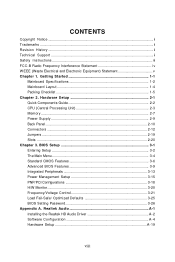
Getting Started 1-1 Mainboard Specifications 1-2 Mainboard Layout 1-4 Packing Checklist 1-5 Chapter 2. BIOS Setup 3-1 Entering Setup ...3-2 The Main Menu ...3-4 Standard CMOS Features 3-6 Advanced BIOS Features 3-9 Integrated Peripherals 3-13 Power Management Setup 3-15 PNP/PCI Configurations 3-18 H/W Monitor ...3-20 Frequency/Voltage Control 3-21 Load Fail-Safe/ Optimized Defaults 3-25 BIOS Setting Password 3-26 Appendix A. Realtek Audio A-1 Installing the Realtek HD Audio Driver A-2 Software Configuration A-4 Hardware Setup A-19 viii Hardware Setup 2-1 Quick ...
Getting Started 1-1 Mainboard Specifications 1-2 Mainboard Layout 1-4 Packing Checklist 1-5 Chapter 2. BIOS Setup 3-1 Entering Setup ...3-2 The Main Menu ...3-4 Standard CMOS Features 3-6 Advanced BIOS Features 3-9 Integrated Peripherals 3-13 Power Management Setup 3-15 PNP/PCI Configurations 3-18 H/W Monitor ...3-20 Frequency/Voltage Control 3-21 Load Fail-Safe/ Optimized Defaults 3-25 BIOS Setting Password 3-26 Appendix A. Realtek Audio A-1 Installing the Realtek HD Audio Driver A-2 Software Configuration A-4 Hardware Setup A-19 viii Hardware Setup 2-1 Quick ...

User Guide
Page 9
Appendix B. Dual Core Center B-1 Activating Dual Core Center B-2 Main ...B-3 DOT (Dynamic OverClocking B-5 Clock ...B-6 Voltage ...B-7 FAN Speed ...B-8 Temperature ...B-9 User Profile ...B-10 Appendix C. Intel ICH7R SATA RAID C-1 ICH7R Introduction C-2 BIOS Configuration C-3 Installing Software C-9 RAID Migration Instructions C-15 Degraded RAID Array C-22 ix
Appendix B. Dual Core Center B-1 Activating Dual Core Center B-2 Main ...B-3 DOT (Dynamic OverClocking B-5 Clock ...B-6 Voltage ...B-7 FAN Speed ...B-8 Temperature ...B-9 User Profile ...B-10 Appendix C. Intel ICH7R SATA RAID C-1 ICH7R Introduction C-2 BIOS Configuration C-3 Installing Software C-9 RAID Migration Instructions C-15 Degraded RAID Array C-22 ix

User Guide
Page 10
Designed to fit the advanced Intel® Core 2 Quad/ Core 2 Due/ Pentium and Celeron processor, the G31M Series deliver a high performance and professional desktop platform solution. 1-1 The G31M Series m ainboards are based on Intel® G31 & ICH7/ ICH7R (optional) chipsets for choosing the G31M Series (MS-7379 v2.X) Micro ATX m ainboard. Getting Started Chapter 1 Getting Started Thank you for optimal system efficiency.
Designed to fit the advanced Intel® Core 2 Quad/ Core 2 Due/ Pentium and Celeron processor, the G31M Series deliver a high performance and professional desktop platform solution. 1-1 The G31M Series m ainboards are based on Intel® G31 & ICH7/ ICH7R (optional) chipsets for choosing the G31M Series (MS-7379 v2.X) Micro ATX m ainboard. Getting Started Chapter 1 Getting Started Thank you for optimal system efficiency.

User Guide
Page 11
c om . North Bridge: Intel® G31 chipset - p hp?func =t est report ) LAN - Supports Ultra DMA 66/100 mode - Supports storage and data transfers at up to 300MB/s Floppy - 1 floppy port - Supports ...
c om . North Bridge: Intel® G31 chipset - p hp?func =t est report ) LAN - Supports Ultra DMA 66/100 mode - Supports storage and data transfers at up to 300MB/s Floppy - 1 floppy port - Supports ...

User Guide
Page 12
Mircro-ATX (24.4 cm X 21.5 cm) Mounting - 6 mounting holes 1-3 Supports TPM Form Factor - SATA1~4 support RAID 0/ /1/ 10/ 5 mode Connectors Back panel - 1 PS/2 mouse port - 1 PS/2 keyboard port - 1 COM port - 1 VGA port - 4 USB 2.0 ports - 1 LAN jack - 6 flexible audio jacks On-Board Pinheaders/ Connectors - 1 Parallel port pinheader supporting SPP/EPP/ECP mode - 2 USB 2.0 pinheaders - 1 CD-In pinheader - 1 Front Panel Audio pinheader - 1 SPDIF-Out pinheader - 1 Chassis Intrusion Switch pinheader Slots - 1 PCI Express x16 slot - 1 PCI Express x1 slot - 2 PCI slots (support 3.3V/ 5V PCI bus...
Mircro-ATX (24.4 cm X 21.5 cm) Mounting - 6 mounting holes 1-3 Supports TPM Form Factor - SATA1~4 support RAID 0/ /1/ 10/ 5 mode Connectors Back panel - 1 PS/2 mouse port - 1 PS/2 keyboard port - 1 COM port - 1 VGA port - 4 USB 2.0 ports - 1 LAN jack - 6 flexible audio jacks On-Board Pinheaders/ Connectors - 1 Parallel port pinheader supporting SPP/EPP/ECP mode - 2 USB 2.0 pinheaders - 1 CD-In pinheader - 1 Front Panel Audio pinheader - 1 SPDIF-Out pinheader - 1 Chassis Intrusion Switch pinheader Slots - 1 PCI Express x16 slot - 1 PCI Express x1 slot - 2 PCI slots (support 3.3V/ 5V PCI bus...

User Guide
Page 13
MS-7379 Mainboard Mainboard Layout Top : mouse Bottom: keyboard COM1 JLPT1 CPUFAN1 SYSFAN1 IDE1 VGA Port USB ports T: LAN jack B: USB ports LAN Chip JPW1 Intel G31 JSP1 JTPM1 (optional) JCI1 Winbond W83627DHG PCI _E1 PCI _E2 PCI 1 Codec PCI 2 JAUD1 CD_IN1 ATX1 DIMM1 DIMM2 B ATT + Intel ICH7/ IC H7 R (optional) SATA4 SATA3 SATA1 SATA2 FDD 1 JUSB2 JUSB1 JFP1 JFP2 JBAT1 G31M Series (MS-7379 v2.X) M-ATX Mainboard 1-4
MS-7379 Mainboard Mainboard Layout Top : mouse Bottom: keyboard COM1 JLPT1 CPUFAN1 SYSFAN1 IDE1 VGA Port USB ports T: LAN jack B: USB ports LAN Chip JPW1 Intel G31 JSP1 JTPM1 (optional) JCI1 Winbond W83627DHG PCI _E1 PCI _E2 PCI 1 Codec PCI 2 JAUD1 CD_IN1 ATX1 DIMM1 DIMM2 B ATT + Intel ICH7/ IC H7 R (optional) SATA4 SATA3 SATA1 SATA2 FDD 1 JUSB2 JUSB1 JFP1 JFP2 JBAT1 G31M Series (MS-7379 v2.X) M-ATX Mainboard 1-4

User Guide
Page 14
Your packing contents may vary depending on the m odel you purchased. 1-5 Packing Checklist Getting Started MSI motherboard MSI Driver/Utility CD SATA Cable (Optional) Power Cable Back IO Shield Standard Cable for IDE Devices User's Guide USB Bracket (Optional) Parallel Port Bracket (Optional) * The pictures are for reference only.
Your packing contents may vary depending on the m odel you purchased. 1-5 Packing Checklist Getting Started MSI motherboard MSI Driver/Utility CD SATA Cable (Optional) Power Cable Back IO Shield Standard Cable for IDE Devices User's Guide USB Bracket (Optional) Parallel Port Bracket (Optional) * The pictures are for reference only.

User Guide
Page 15
While doing the installation, be careful in the wrong orientation, the components will not work properly. For some components, if you with the information about hardware setup procedures. Static electricity may damage the components. 2-1 Use a grounded wrist strap before handling computer components. Hardware Setup Chapter 2 Hardware Setup This chapter provides you install in holding the components and follow the installation procedures.
While doing the installation, be careful in the wrong orientation, the components will not work properly. For some components, if you with the information about hardware setup procedures. Static electricity may damage the components. 2-1 Use a grounded wrist strap before handling computer components. Hardware Setup Chapter 2 Hardware Setup This chapter provides you install in holding the components and follow the installation procedures.
User Guide
Page 17
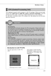
For the latest information about CPU, please visit http://global.msi.com.tw/index. Make sure that you do not guarantee the damages or risks caused by inadequate operation or beyond product specifications is the Pin 1 ...
For the latest information about CPU, please visit http://global.msi.com.tw/index. Make sure that you do not guarantee the damages or risks caused by inadequate operation or beyond product specifications is the Pin 1 ...

User Guide
Page 18
MS-7379 Mainboard CPU & Cooler Installation W hen you install the CPU, always cover it to protect the contact from lever hinge side (as the arrow shows). 3. The CPU socket has a plastic cap on your system. 2. Open the load lever. The pins of the CPU land side cover depends on it to prevent overheating. Do not touch the CPU socket pins to install the CPU & cooler correctly. Before you are installing the CPU, make sure the CPU has a cooler attached on your CPU packing. 2-4 The availability of socket reveal. 4. Meanwhile, do not forget to apply some thermal paste on...
MS-7379 Mainboard CPU & Cooler Installation W hen you install the CPU, always cover it to protect the contact from lever hinge side (as the arrow shows). 3. The CPU socket has a plastic cap on your system. 2. Open the load lever. The pins of the CPU land side cover depends on it to prevent overheating. Do not touch the CPU socket pins to install the CPU & cooler correctly. Before you are installing the CPU, make sure the CPU has a cooler attached on your CPU packing. 2-4 The availability of socket reveal. 4. Meanwhile, do not forget to apply some thermal paste on...

User Guide
Page 19
Be sure to grasp on the edge of the CPU base. alignment key 7. Cover the load plate onto the p ac kage. 2-5 Note that the alignment keys are matched. Lift the load lever up and open the load plate. 6. Visually inspect if the CPU is seated well into the socket. If not, take out the CPU with pure vertical motion and reinstall. 8. Hardware Setup 5. After confirming the CPU direction for correct mating, put down the CPU in the socket housing frame.
Be sure to grasp on the edge of the CPU base. alignment key 7. Cover the load plate onto the p ac kage. 2-5 Note that the alignment keys are matched. Lift the load lever up and open the load plate. 6. Visually inspect if the CPU is seated well into the socket. If not, take out the CPU with pure vertical motion and reinstall. 8. Hardware Setup 5. After confirming the CPU direction for correct mating, put down the CPU in the socket housing frame.

User Guide
Page 20
Press the four hooks down the load lever lightly onto the load plate, and then secure the lever with the hook under retention tab. 10. Turn over the mainboard to fasten the cooler. MS-7379 Mainboard 9. Press down to confirm that the clip-ends are for demonstration of the CPU/ cooler installation only. The appearance of the mainboard. 11. Read the CPU status in Figure 1) to lock the h ook s . 12. Push down the cooler until its four clips get wedged into the holes of your CPU socket pin with the heatsink. Mainboard photos shown in this section are correctly ...
Press the four hooks down the load lever lightly onto the load plate, and then secure the lever with the hook under retention tab. 10. Turn over the mainboard to fasten the cooler. MS-7379 Mainboard 9. Press down to confirm that the clip-ends are for demonstration of the CPU/ cooler installation only. The appearance of the mainboard. 11. Read the CPU status in Figure 1) to lock the h ook s . 12. Push down the cooler until its four clips get wedged into the holes of your CPU socket pin with the heatsink. Mainboard photos shown in this section are correctly ...

User Guide
Page 21
For more information on compatible components, please visit http://global.msi.com. tw/index.php?func=testreport DDR2 240-pin, 1.8V 64x2=128 pin 56x2=112 pin Dual-Channel: Channel A in ORANGE Dual-Channel mode Population ...
For more information on compatible components, please visit http://global.msi.com. tw/index.php?func=testreport DDR2 240-pin, 1.8V 64x2=128 pin 56x2=112 pin Dual-Channel: Channel A in ORANGE Dual-Channel mode Population ...

User Guide
Page 22
In Dual-Channel mode, make sure that you install memory modules of the DIMM slot will automatically close. The plastic clip at each DIMM is installed with DDR and the DDR2 standard is deeply inserted in the DDR2 DIMM slots. - DDR2 memory modules are not interchangeable with a 1GB memory module. 2-8 Important You can barely see the golden finger if the memory module is properly inserted in different channel DIMM slots. - You should always install DDR2 memory modules in the DIMM slot. Volt Notch Important - Due to the chipset resource deployment, the system density will ...
In Dual-Channel mode, make sure that you install memory modules of the DIMM slot will automatically close. The plastic clip at each DIMM is installed with DDR and the DDR2 standard is deeply inserted in the DDR2 DIMM slots. - DDR2 memory modules are not interchangeable with a 1GB memory module. 2-8 Important You can barely see the golden finger if the memory module is properly inserted in different channel DIMM slots. - You should always install DDR2 memory modules in the DIMM slot. Volt Notch Important - Due to the chipset resource deployment, the system density will ...

User Guide
Page 23
If you like to use the 20-pin ATX power supply as you 'd like . You may use the 20-pin ATX power supply, please plug your power supply along with pin 1 & pin 13 (refer to the image at the right hand). 12 ATX1 1 Pin Definition 24 PIN SIGNAL PIN SIGNAL 1 +3.3V 13 +3.3V 2 +3.3V 3 GND 14 -12V 15 GND 4 +5V 5 GND 16 PS-ON# 17 GND 6 +5V 7 GND 18 GND 19 GND 8 PW R OK 20 Res 9 5VSB 21 +5V 10 +12V 11 +12V 13 12 +3.3V 22 +5V 23 +5V 24 GND ATX 12V Power Connector: JPW1 This 12V power connector is used to provide power to the CPU. 42 Pin ...
If you like to use the 20-pin ATX power supply as you 'd like . You may use the 20-pin ATX power supply, please plug your power supply along with pin 1 & pin 13 (refer to the image at the right hand). 12 ATX1 1 Pin Definition 24 PIN SIGNAL PIN SIGNAL 1 +3.3V 13 +3.3V 2 +3.3V 3 GND 14 -12V 15 GND 4 +5V 5 GND 16 PS-ON# 17 GND 6 +5V 7 GND 18 GND 19 GND 8 PW R OK 20 Res 9 5VSB 21 +5V 10 +12V 11 +12V 13 12 +3.3V 22 +5V 23 +5V 24 GND ATX 12V Power Connector: JPW1 This 12V power connector is used to provide power to the CPU. 42 Pin ...

User Guide
Page 24
ActivityIndicator nection to it. On (steady state) LAN link is for attaching USB devices such as keyboard, mouse, or other serial devices directly to the connector. You can connect a network cable to the Local Area Network (LAN). MS-7379 Mainboard Back Panel Mouse Keyboard Serial Port VGA Port LAN Line-In RS-Out Line-Out CS-Out USB Porta Mic SS-Out M ouse/K ey boar d The standard PS/2® mouse/keyboard DIN connector is established. USB Port The USB (Universal Serial Bus) port is not established. Link Indicator LED Color Left Yellow Green Right Orange LED ...
ActivityIndicator nection to it. On (steady state) LAN link is for attaching USB devices such as keyboard, mouse, or other serial devices directly to the connector. You can connect a network cable to the Local Area Network (LAN). MS-7379 Mainboard Back Panel Mouse Keyboard Serial Port VGA Port LAN Line-In RS-Out Line-Out CS-Out USB Porta Mic SS-Out M ouse/K ey boar d The standard PS/2® mouse/keyboard DIN connector is established. USB Port The USB (Universal Serial Bus) port is not established. Link Indicator LED Color Left Yellow Green Right Orange LED ...