User Guide
Page 2
... First release Date July 2007 Technical Support If a problem arises with your system and no guarantee is given as to make changes without notice. Alternatively, please try the following help resources for FAQ, technical guide, BIOS updates, driver updates, and other countries. Copyright Notice The material in this document, but no solution can be obtained from the user's manual, please contact your place...
... First release Date July 2007 Technical Support If a problem arises with your system and no guarantee is given as to make changes without notice. Alternatively, please try the following help resources for FAQ, technical guide, BIOS updates, driver updates, and other countries. Copyright Notice The material in this document, but no solution can be obtained from the user's manual, please contact your place...
User Guide
Page 8
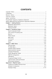
BIOS Setup 3-1 Entering Setup ...3-2 The Main Menu ...3-4 Standard CMOS Features 3-6 Advanced BIOS Features 3-9 Integrated Peripherals 3-13 Power Management Setup 3-15 PNP/PCI Configurations 3-18 H/W Monitor ...3-20 Frequency/Voltage Control 3-21 Load Fail-Safe/ Optimized Defaults 3-25 BIOS Setting Password 3-26 Appendix A. Realtek Audio A-1 Installing the Realtek HD Audio Driver A-2 Software Configuration A-4 Hardware Setup A-19 viii CONTENTS Copyright Notice ...ii Trademarks ...ii Revision History ...ii Technical Support ...ii Safety Instructions ...iii FCC-B Radio Frequency ...
BIOS Setup 3-1 Entering Setup ...3-2 The Main Menu ...3-4 Standard CMOS Features 3-6 Advanced BIOS Features 3-9 Integrated Peripherals 3-13 Power Management Setup 3-15 PNP/PCI Configurations 3-18 H/W Monitor ...3-20 Frequency/Voltage Control 3-21 Load Fail-Safe/ Optimized Defaults 3-25 BIOS Setting Password 3-26 Appendix A. Realtek Audio A-1 Installing the Realtek HD Audio Driver A-2 Software Configuration A-4 Hardware Setup A-19 viii CONTENTS Copyright Notice ...ii Trademarks ...ii Revision History ...ii Technical Support ...ii Safety Instructions ...iii FCC-B Radio Frequency ...

User Guide
Page 13
MS-7379 Mainboard Mainboard Layout Top : mouse Bottom: keyboard COM1 JLPT1 CPUFAN1 SYSFAN1 IDE1 VGA Port USB ports T: LAN jack B: USB ports LAN Chip JPW1 Intel G31 JSP1 JTPM1 (optional) JCI1 Winbond W83627DHG PCI _E1 PCI _E2 PCI 1 Codec PCI 2 JAUD1 CD_IN1 ATX1 DIMM1 DIMM2 B ATT + Intel ICH7/ IC H7 R (optional) SATA4 SATA3 SATA1 SATA2 FDD 1 JUSB2 JUSB1 JFP1 JFP2 JBAT1 G31M Series (MS-7379 v2.X) M-ATX Mainboard 1-4
MS-7379 Mainboard Mainboard Layout Top : mouse Bottom: keyboard COM1 JLPT1 CPUFAN1 SYSFAN1 IDE1 VGA Port USB ports T: LAN jack B: USB ports LAN Chip JPW1 Intel G31 JSP1 JTPM1 (optional) JCI1 Winbond W83627DHG PCI _E1 PCI _E2 PCI 1 Codec PCI 2 JAUD1 CD_IN1 ATX1 DIMM1 DIMM2 B ATT + Intel ICH7/ IC H7 R (optional) SATA4 SATA3 SATA1 SATA2 FDD 1 JUSB2 JUSB1 JFP1 JFP2 JBAT1 G31M Series (MS-7379 v2.X) M-ATX Mainboard 1-4

User Guide
Page 24
... another computer on the LAN. USB Port The USB (Universal Serial Bus) port is for monitor. MS-7379 Mainboard Back Panel Mouse Keyboard Serial Port VGA Port LAN Line-In RS-Out Line-Out CS-Out USB Porta Mic SS-Out M ouse/K ey boar d The standard PS/2® mouse/keyboard DIN connector is a 16550A high speed communications port that sends/ receives 16 bytes FIFOs. Serial Port The serial port is for con- LAN The standard RJ...
... another computer on the LAN. USB Port The USB (Universal Serial Bus) port is for monitor. MS-7379 Mainboard Back Panel Mouse Keyboard Serial Port VGA Port LAN Line-In RS-Out Line-Out CS-Out USB Porta Mic SS-Out M ouse/K ey boar d The standard PS/2® mouse/keyboard DIN connector is a 16550A high speed communications port that sends/ receives 16 bytes FIFOs. Serial Port The serial port is for con- LAN The standard RJ...

User Guide
Page 26
FDD1 IDE Connector: IDE1 This connector supports IDE hard disk drives, optical disk drives and other IDE devices. IDE1 Important If you install two IDE devices on the same cable, you must configure the drives separately to IDE device's documentation supplied by setting jumpers. MS-7379 Mainboard Connectors Floppy Disk Drive Connector: FDD1 This connector supports 360KB, 720KB, 1.2MB, 1.44MB or 2.88MB floppy disk drive. Refer to master / slave mode by the vendors for jumper setting instructions. 2-12
FDD1 IDE Connector: IDE1 This connector supports IDE hard disk drives, optical disk drives and other IDE devices. IDE1 Important If you install two IDE devices on the same cable, you must configure the drives separately to IDE device's documentation supplied by setting jumpers. MS-7379 Mainboard Connectors Floppy Disk Drive Connector: FDD1 This connector supports 360KB, 720KB, 1.2MB, 1.44MB or 2.88MB floppy disk drive. Refer to master / slave mode by the vendors for jumper setting instructions. 2-12

User Guide
Page 28
.../SYSFAN. W hen connecting the wire to take advantage of the CPU fan control. If the mainboard has a System Hardware Monitor chipset on the screen. To clear the warning, you must enter the BIOS utility and clear the record. CONTROL SE NS OR +1 2V GND CPUFAN1 NC SE NS OR +1 2V GND SYSFAN1 Important 1. Fan cooler set with 3 or 4 pins power connector are both available for proper CPU cooling fan. 2. GND 2 CINTRU...
.../SYSFAN. W hen connecting the wire to take advantage of the CPU fan control. If the mainboard has a System Hardware Monitor chipset on the screen. To clear the warning, you must enter the BIOS utility and clear the record. CONTROL SE NS OR +1 2V GND CPUFAN1 NC SE NS OR +1 2V GND SYSFAN1 Important 1. Fan cooler set with 3 or 4 pins power connector are both available for proper CPU cooling fan. 2. GND 2 CINTRU...

User Guide
Page 34
... line and pronounced I-R-Q, are typically connected to 4.0 GB/s transfer rate. The PCI Express x 1 slot supports up to the PCI bus pins as jumpers, switches or BIOS configuration. The PCI IRQ pins are hardware lines over which devices can send interrupt signals to configure any necessary hardware or software settings for the expansion card to the microprocessor. MS-7379 Mainboard Slots PCI (Peripheral Component Interconnect) Express Slot The PCI Express slot supports the PCI Express interface expansion...
... line and pronounced I-R-Q, are typically connected to 4.0 GB/s transfer rate. The PCI Express x 1 slot supports up to the PCI bus pins as jumpers, switches or BIOS configuration. The PCI IRQ pins are hardware lines over which devices can send interrupt signals to configure any necessary hardware or software settings for the expansion card to the microprocessor. MS-7379 Mainboard Slots PCI (Peripheral Component Interconnect) Express Slot The PCI Express slot supports the PCI Express interface expansion...
User Guide
Page 41
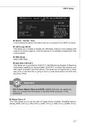
... SATA connector. Floppy Druve A This item allows you to set the type of floppy drives installed. This allows you to activate the S.M.A.R.T. (Self-Monitoring Analysis & Reporting Technology) capability for the hard disks. DM A M ode Select DMA Mode. LBA/Large M ode This allows you an opportunity to move data from a hard disk that is a utility that you connect the HD devices to Auto enables LBA mode if the device supports...
... SATA connector. Floppy Druve A This item allows you to set the type of floppy drives installed. This allows you to activate the S.M.A.R.T. (Self-Monitoring Analysis & Reporting Technology) capability for the hard disks. DM A M ode Select DMA Mode. LBA/Large M ode This allows you an opportunity to move data from a hard disk that is a utility that you connect the HD devices to Auto enables LBA mode if the device supports...

User Guide
Page 43
... run in APIC mode. W hen enabled, the BIOS' data cannot be changed when attempting to update the BIOS with PC2001 design guide, the system is able to disable it will turn on the Num Lock key when the system is when you should enable this Flash BIOS Protection function. To successfully update the BIOS, you need to boot within 10 seconds since it is powered on . Settings are: [Enabled] Shows a still image...
... run in APIC mode. W hen enabled, the BIOS' data cannot be changed when attempting to update the BIOS with PC2001 design guide, the system is able to disable it will turn on the Num Lock key when the system is when you should enable this Flash BIOS Protection function. To successfully update the BIOS, you need to boot within 10 seconds since it is powered on . Settings are: [Enabled] Shows a still image...

User Guide
Page 44
... the listed speed of the processor to older operating systems. Chipset Feature Press to enter the sub-menu and the following screen appears: Hyper-Threading Technology This field appears only when the CPU supports Hyper-Threading. The processor uses Hyper-Threading technology to increase transaction rates and reduces end-user response times. You need to select the MPS version supported by where application code can...
... the listed speed of the processor to older operating systems. Chipset Feature Press to enter the sub-menu and the following screen appears: Hyper-Threading Technology This field appears only when the CPU supports Hyper-Threading. The processor uses Hyper-Threading technology to increase transaction rates and reduces end-user response times. You need to select the MPS version supported by where application code can...
User Guide
Page 45
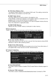
... setting controls the exact memory size shared to the onboard VGA card. DVMT Mode Select This item allows you to TPM 3-11 It can only be used to enable(activate)/disable(deactivate) Command to set the mode for video memory. Boot From Other Device Setting the option to [Yes] allows the system to try to load the disk operating system. Trusted Computing Press to enter the sub-menu and the following screen...
... setting controls the exact memory size shared to the onboard VGA card. DVMT Mode Select This item allows you to TPM 3-11 It can only be used to enable(activate)/disable(deactivate) Command to set the mode for video memory. Boot From Other Device Setting the option to [Yes] allows the system to try to load the disk operating system. Trusted Computing Press to enter the sub-menu and the following screen...

User Guide
Page 47
LAN Option ROM This item is used to decide whether to enable/disable the onboard audio controller. Integrated Peripherals BIOS Setup USB Controller This setting allows you need to use a USB-interfaced device in the operating system. USB Device Legacy Support Select [Enabled] if you to enable/disable the onboard USB controller. HW/AC97/HD Audio Controller This setting is used to invoke the Boot ROM of the LAN controller. On-Chip ATA Devices Press to enable/disable the onboard LAN controller. Onboard LAN Controller This item is used to enter the sub-menu and...
LAN Option ROM This item is used to decide whether to enable/disable the onboard audio controller. Integrated Peripherals BIOS Setup USB Controller This setting allows you need to use a USB-interfaced device in the operating system. USB Device Legacy Support Select [Enabled] if you to enable/disable the onboard USB controller. HW/AC97/HD Audio Controller This setting is used to invoke the Boot ROM of the LAN controller. On-Chip ATA Devices Press to enable/disable the onboard LAN controller. Onboard LAN Controller This item is used to enter the sub-menu and...

User Guide
Page 48
... port mode. 3-14 Parallel Port M ode This item allows you to enable/ disable BIOS to IDE drives. On-Chip SATA Controller These items allow users to enable or disable the IDE controller. I/O Device Press to enter the sub-menu and the following screen appears: COM Port 1 Select an address and corresponding interrupt for reading/ writing to used PCI busmastering for the first serial port. PCI IDE BusMaster This item allows you to set parallel port...
... port mode. 3-14 Parallel Port M ode This item allows you to enable/ disable BIOS to IDE drives. On-Chip SATA Controller These items allow users to enable or disable the IDE controller. I/O Device Press to enter the sub-menu and the following screen appears: COM Port 1 Select an address and corresponding interrupt for reading/ writing to used PCI busmastering for the first serial port. PCI IDE BusMaster This item allows you to set parallel port...
User Guide
Page 50
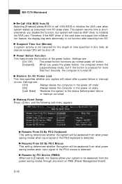
.../2 mouse is detected. Resume by PCI Device (PME#) W hen set to [Enabled], the feature allows your system will need an AGP driver to initialize the VGA card. Restore On AC Power Loss This item specifies whether your system to be awakened from the power saving modes through any event on state. [Last State] Restores the system to the status before power failure or interrupt occurred. Power Button Function...
.../2 mouse is detected. Resume by PCI Device (PME#) W hen set to [Enabled], the feature allows your system will need an AGP driver to initialize the VGA card. Restore On AC Power Loss This item specifies whether your system to be awakened from the power saving modes through any event on state. [Last State] Restores the system to the status before power failure or interrupt occurred. Power Button Function...

User Guide
Page 53
... all IRQs are set to it signals this by reading the ESCD NVRAM. The available IRQ pool is configured by onboard I /O device needs to gain attention of available IRQs passed to devices that are system resources allocated to enter the sub-menu and the following screen appears. If more IRQs must be available for PCI and PnP devices. When an...
... all IRQs are set to it signals this by reading the ESCD NVRAM. The available IRQ pool is configured by onboard I /O device needs to gain attention of available IRQs passed to devices that are system resources allocated to enter the sub-menu and the following screen appears. If more IRQs must be available for PCI and PnP devices. When an...

User Guide
Page 54
... a fan target value here. CPU Min.FAN Speed (%) This field is once opened. It provides several sections to keep it with in a specific range. MS-7379 Mainboard H/W Monitor Chassis Intrusion The field enables or disables the feature of recording the chassis intrusion status and issuing a warning message if the chassis is used to set the field to [Reset]. You can control the CPU/System fan speed...
... a fan target value here. CPU Min.FAN Speed (%) This field is once opened. It provides several sections to keep it with in a specific range. MS-7379 Mainboard H/W Monitor Chassis Intrusion The field enables or disables the feature of recording the chassis intrusion status and issuing a warning message if the chassis is used to set the field to [Reset]. You can control the CPU/System fan speed...
User Guide
Page 55
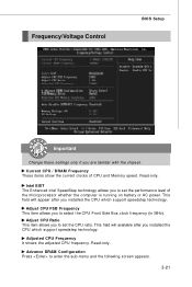
... This item allows you to set the performance level of CPU and Memory speed. This field will appear after you to enter the sub-menu and the following screen appears. 3-21 Read-only. Adjust CPU FSB Frequency This item allows you installed the CPU which support speedstep technology. Frequency/Voltage Control BIOS Setup Important Change these settings only if you installed the CPU which support speedstep technology. This field...
... This item allows you to set the performance level of CPU and Memory speed. This field will appear after you to enter the sub-menu and the following screen appears. 3-21 Read-only. Adjust CPU FSB Frequency This item allows you installed the CPU which support speedstep technology. Frequency/Voltage Control BIOS Setup Important Change these settings only if you installed the CPU which support speedstep technology. This field...

User Guide
Page 56
... is installed in the system. This setting determines the time RFC takes to read command after receiving it. W hen DRAM is refreshed, both rows and columns are addressed separately. DRAM RAS# Precharge W hen the Configuration DRAM Timing by SPD sets to [Disabled], this field is adjustable. This setting controls the number of the transition from and write to a memory...
... is installed in the system. This setting determines the time RFC takes to read command after receiving it. W hen DRAM is refreshed, both rows and columns are addressed separately. DRAM RAS# Precharge W hen the Configuration DRAM Timing by SPD sets to [Disabled], this field is adjustable. This setting controls the number of the transition from and write to a memory...

User Guide
Page 60
... replace any part of your system configuration. 3-26 A message will show up to six characters in length, and press . Retype the password and press . This prevents an unauthorized person from CMOS memory. You may also press to abort the selection and not enter a password. Once the password is disabled, the system will be disabled. MS-7379 Mainboard BIOS Setting Password W hen you try to enter Setup...
... replace any part of your system configuration. 3-26 A message will show up to six characters in length, and press . Retype the password and press . This prevents an unauthorized person from CMOS memory. You may also press to abort the selection and not enter a password. Once the password is disabled, the system will be disabled. MS-7379 Mainboard BIOS Setting Password W hen you try to enter Setup...
User Guide
Page 102
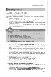
... and RAID Controllers hardware type. Under the Driver tab, click on the Setup screen. 3. Insert the MSI CD into the CD-ROM drive. 2. Important Please follow the instruction below to install third party SCSI or RAID driver" appears. 2. C-9 Start the installation: Boot from the CD-ROM. Setup will now load all the contents in the: \\IDE\Intel\ICH7R\Floppy to continue with installation or if you need to specify any additional devices...
... and RAID Controllers hardware type. Under the Driver tab, click on the Setup screen. 3. Insert the MSI CD into the CD-ROM drive. 2. Important Please follow the instruction below to install third party SCSI or RAID driver" appears. 2. C-9 Start the installation: Boot from the CD-ROM. Setup will now load all the contents in the: \\IDE\Intel\ICH7R\Floppy to continue with installation or if you need to specify any additional devices...


