User Manual
Page 1
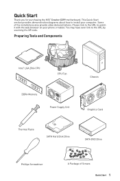
... computer. This Quick Start section provides demonstration diagrams about how to the URL by scanning the QR code. Quick Start Thank you for purchasing the MSI® Creator X299 motherboard. You may have even link to install your phone or tablet. Preparing Tools and Components Intel® LGA 2066 CPU CPU Fan DDR4 Memory...
... computer. This Quick Start section provides demonstration diagrams about how to the URL by scanning the QR code. Quick Start Thank you for purchasing the MSI® Creator X299 motherboard. You may have even link to install your phone or tablet. Preparing Tools and Components Intel® LGA 2066 CPU CPU Fan DDR4 Memory...
User Manual
Page 2
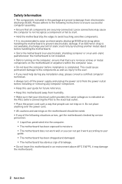
... Start If an ESD wrist strap is not available, discharge yourself of static electricity by the edges to moisture. ▪▪The motherboard does not work well or you need help during any installation step, please consult a certified computer technician. ∙∙Always turn off ... the power cord from electrostatic discharge (ESD). Do not place anything over the power cord. ∙∙All cautions and warnings on the motherboard or anywhere within the computer case. ∙∙Do not boot the computer before installing or removing any of the following instructions to ensure...
... Start If an ESD wrist strap is not available, discharge yourself of static electricity by the edges to moisture. ▪▪The motherboard does not work well or you need help during any installation step, please consult a certified computer technician. ∙∙Always turn off ... the power cord from electrostatic discharge (ESD). Do not place anything over the power cord. ∙∙All cautions and warnings on the motherboard or anywhere within the computer case. ∙∙Do not boot the computer before installing or removing any of the following instructions to ensure...

User Manual
Page 6
Installing the Motherboard 1 2 BAT1 6 Quick Start
Installing the Motherboard 1 2 BAT1 6 Quick Start

User Manual
Page 12
Contents Quick Start...1 Preparing Tools and Components 1 Safety Information 2 Installing a Processor 3 Installing DDR4 memory 4 Connecting the Front Panel Header 5 Installing the Motherboard 6 Connecting the Power Connectors 7 Installing SATA Drives 8 Installing a Graphics Card 9 Connecting Peripheral Devices 10 Power On...11 Specifications...15 JCORSAIR1 Connector Specification 21 Package contents ...
Contents Quick Start...1 Preparing Tools and Components 1 Safety Information 2 Installing a Processor 3 Installing DDR4 memory 4 Connecting the Front Panel Header 5 Installing the Motherboard 6 Connecting the Power Connectors 7 Installing SATA Drives 8 Installing a Graphics Card 9 Connecting Peripheral Devices 10 Power On...11 Specifications...15 JCORSAIR1 Connector Specification 21 Package contents ...
User Manual
Page 21
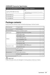
... the number of LED strips exceeds 8. 6 6 6 Package contents Please check the contents of the above items are damaged or missing, please contact your motherboard package. It should contain: Motherboard Creator X299 User manual 1 Documentation Quick installation guide 1 Application USB drive with drivers & utilities 1 SATA 6Gb/s cable 4 LED JRGB Y cable 1 LED JCORSAIR cable 1 Cables LED...
... the number of LED strips exceeds 8. 6 6 6 Package contents Please check the contents of the above items are damaged or missing, please contact your motherboard package. It should contain: Motherboard Creator X299 User manual 1 Documentation Quick installation guide 1 Application USB drive with drivers & utilities 1 SATA 6Gb/s cable 4 LED JRGB Y cable 1 LED JCORSAIR cable 1 Cables LED...

User Manual
Page 29
... prevent overheating and maintain system stability. ∙∙Confirm that all other system components can seriously damage the CPU and motherboard. MSI will deal with Return Merchandise Authorization (RMA) requests if only the motherboard comes with the CPU before installing or removing the CPU. ∙∙Please retain the CPU protective cap after...
... prevent overheating and maintain system stability. ∙∙Confirm that all other system components can seriously damage the CPU and motherboard. MSI will deal with Return Merchandise Authorization (RMA) requests if only the motherboard comes with the CPU before installing or removing the CPU. ∙∙Please retain the CPU protective cap after...

User Manual
Page 35
Connect the U.2 cable to power adapter cable. Connect the U.2 cable to the U.2 connector on the motherboard. 2. Connect the U.2 cable to power adapter cable Overview of Components 35 U.2 SSD U.2 Connector 1 2 U.2 Cable 3 Connect to the U.2 SSD. 3. Each connector can connect to one PCIe 3.0 x4 NVMe storage device. ⚽⚽Video Demonstration Watch the video to learn how to Install U.2 SSD. http://youtu.be/KgFvKDxymvw Installing U.2 SSD 1. U2_1: U.2 Connector This connector is a U.2 interface port.
Connect the U.2 cable to power adapter cable. Connect the U.2 cable to the U.2 connector on the motherboard. 2. Connect the U.2 cable to power adapter cable Overview of Components 35 U.2 SSD U.2 Connector 1 2 U.2 Cable 3 Connect to the U.2 SSD. 3. Each connector can connect to one PCIe 3.0 x4 NVMe storage device. ⚽⚽Video Demonstration Watch the video to learn how to Install U.2 SSD. http://youtu.be/KgFvKDxymvw Installing U.2 SSD 1. U2_1: U.2 Connector This connector is a U.2 interface port.

User Manual
Page 40
... SATA1 SATA4 SATA3 ⚠⚠Important ∙∙Please do not fold the SATA cable at a 90-degree angle. Each connector can connect to the motherboard for space saving purposes.
... SATA1 SATA4 SATA3 ⚠⚠Important ∙∙Please do not fold the SATA cable at a 90-degree angle. Each connector can connect to the motherboard for space saving purposes.

User Manual
Page 41
... Make sure that all the power cables are securely connected to a proper ATX power supply to ensure stable operation of Components 41 Overview of the motherboard.
... Make sure that all the power cables are securely connected to a proper ATX power supply to ensure stable operation of Components 41 Overview of the motherboard.

User Manual
Page 45
... sure fans are gradient points of Components 45 PWM Mode fan connectors provide constant 12V output and adjust fan speed with speed control signal. This motherboard can be classified as PWM (Pulse Width Modulation) Mode or DC Mode. DC Mode fan connectors control fan speed by changing voltage. However, you can...
... sure fans are gradient points of Components 45 PWM Mode fan connectors provide constant 12V output and adjust fan speed with speed control signal. This motherboard can be classified as PWM (Pulse Width Modulation) Mode or DC Mode. DC Mode fan connectors control fan speed by changing voltage. However, you can...

User Manual
Page 50
Power off the computer and unplug the power cord. 2. Use a jumper cap to default values 1. Remove the jumper cap from a battery located on the motherboard to connect the add-on Card Connector This connector allows you to clear the CMOS memory. POWER1, RESET1: Power Button, Reset Button The Power / Reset ...
Power off the computer and unplug the power cord. 2. Use a jumper cap to default values 1. Remove the jumper cap from a battery located on the motherboard to connect the add-on Card Connector This connector allows you to clear the CMOS memory. POWER1, RESET1: Power Button, Reset Button The Power / Reset ...

User Manual
Page 51
...causes the computer non-bootable, you can shift to the other for details. Before recovering, please download the latest BIOS file that matches your motherboard model from MSI website. Select the M-FLASH tab and click on Yes to start recovering BIOS. 8. Switch to the failed BIOS ROM with Multi-BIOS switch..... 7. Please refer to BIOS section for booting by the steps below. Overview of the USB flash drive. 1. BIOS_SW1: Multi-BIOS Switch This motherboard has two built-in BIOS ROMs. If one is booting up. ∙∙You can also use the Multi-BIOS switch when system is crashed...
...causes the computer non-bootable, you can shift to the other for details. Before recovering, please download the latest BIOS file that matches your motherboard model from MSI website. Select the M-FLASH tab and click on Yes to start recovering BIOS. 8. Switch to the failed BIOS ROM with Multi-BIOS switch..... 7. Please refer to BIOS section for booting by the steps below. Overview of the USB flash drive. 1. BIOS_SW1: Multi-BIOS Switch This motherboard has two built-in BIOS ROMs. If one is booting up. ∙∙You can also use the Multi-BIOS switch when system is crashed...

User Manual
Page 54
... in series. 1 > 2 > 3 > 4 > 5 > 6. Please refer to connect the CORSAIR Individually Addressable Lighting PRO RGB LED strips 5V or CORSAIR RGB fans with MSI's software. 1 1 +5V 2 3 Ground Data CORSAIR RGB Fan Connection CORSAIR RGB LED fan SATA power SYS_FAN SYS_FAN CORSAIR fan hub 4 5 6 SYS_FAN 3 2 1 SYS_FAN ... Fans or RGB LED Lighting PRO strips supported may differ between models. Once all items are connected properly, you to the motherboard specification. ∙∙CORSAIR RGB LED Fan and CORSAIR Lighting Node PRO can control the CORSAIR RGB LED strips and fans ...
... in series. 1 > 2 > 3 > 4 > 5 > 6. Please refer to connect the CORSAIR Individually Addressable Lighting PRO RGB LED strips 5V or CORSAIR RGB fans with MSI's software. 1 1 +5V 2 3 Ground Data CORSAIR RGB Fan Connection CORSAIR RGB LED fan SATA power SYS_FAN SYS_FAN CORSAIR fan hub 4 5 6 SYS_FAN 3 2 1 SYS_FAN ... Fans or RGB LED Lighting PRO strips supported may differ between models. Once all items are connected properly, you to the motherboard specification. ∙∙CORSAIR RGB LED Fan and CORSAIR Lighting Node PRO can control the CORSAIR RGB LED strips and fans ...

User Manual
Page 55
indicates DRAM is not detected or fail. indicates the booting device is not detected or fail. XMP LED Onboard LEDs 55 indicates GPU is enabled. BOOT - JPWRLED1 - VGA - LED power input XMP LED This LED indicates the XMP (Extreme Memory Profile) mode is not detected or fail. indicates CPU is used by retailers to demonstrate onboard LED lights. JPWRLED1: LED power input This connector is not detected or fail. Onboard LEDs EZ Debug LED These LEDs indicate the debug status of the motherboard. DRAM - CPU -
indicates DRAM is not detected or fail. indicates the booting device is not detected or fail. XMP LED Onboard LEDs 55 indicates GPU is enabled. BOOT - JPWRLED1 - VGA - LED power input XMP LED This LED indicates the XMP (Extreme Memory Profile) mode is not detected or fail. indicates CPU is used by retailers to demonstrate onboard LED lights. JPWRLED1: LED power input This connector is not detected or fail. Onboard LEDs EZ Debug LED These LEDs indicate the debug status of the motherboard. DRAM - CPU -

User Manual
Page 63
...Yes to download and install the latest BIOS file. 5. After the flashing process is off before clearing CMOS data. Install and launch MSI CREATOR CENTER. 2. Please refer to perform the BIOS update process. 4. And then save the BIOS file into the USB port. 2. Updating...MSI CREATOR CENTER Before updating: Make sure the LAN driver is already installed and the Internet connection is 100% completed, the system will restart automatically. Click on Download icon to reboot the system. 3. Click on Scan button. 4. Insert the USB flash drive that matches your motherboard model from MSI...
...Yes to download and install the latest BIOS file. 5. After the flashing process is off before clearing CMOS data. Install and launch MSI CREATOR CENTER. 2. Please refer to perform the BIOS update process. 4. And then save the BIOS file into the USB port. 2. Updating...MSI CREATOR CENTER Before updating: Make sure the LAN driver is already installed and the Internet connection is 100% completed, the system will restart automatically. Click on Download icon to reboot the system. 3. Click on Scan button. 4. Insert the USB flash drive that matches your motherboard model from MSI...
User Manual
Page 64
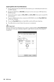
... flash BIOS, and the LED starts flashing. 6. Plug the USB flash drive that matches your motherboard model from the MSI® website. 2. To check your USB flash drive (FAT32 format). 3. Rename the BIOS file to MSI.ROM, and save it to the root of your drive, go to Windows Explorer, right click... on the rear I/O panel. 5. Press the Flash BIOS Button to install CPU and memory.) 4. Please download the latest BIOS file that contains the MSI.ROM file into the Flash BIOS Port on the drive icon and go to Properties. 64 BIOS Setup Updating BIOS with Flash BIOS Button 1.
... flash BIOS, and the LED starts flashing. 6. Plug the USB flash drive that matches your motherboard model from the MSI® website. 2. To check your USB flash drive (FAT32 format). 3. Rename the BIOS file to MSI.ROM, and save it to the root of your drive, go to Windows Explorer, right click... on the rear I/O panel. 5. Press the Flash BIOS Button to install CPU and memory.) 4. Please download the latest BIOS file that contains the MSI.ROM file into the Flash BIOS Port on the drive icon and go to Properties. 64 BIOS Setup Updating BIOS with Flash BIOS Button 1.

User Manual
Page 67
... you to manage overclocking profiles. ▪▪HARDWARE MONITOR - allows you to set the speeds of fans and monitor voltages of installed devices on this motherboard. ∙∙ Menu display - Advanced Mode Press Setup Mode switch or F7 function key can switch between EZ Mode and Advanced Mode in BIOS setup...
... you to manage overclocking profiles. ▪▪HARDWARE MONITOR - allows you to set the speeds of fans and monitor voltages of installed devices on this motherboard. ∙∙ Menu display - Advanced Mode Press Setup Mode switch or F7 function key can switch between EZ Mode and Advanced Mode in BIOS setup...

User Manual
Page 68
... switch between date elements. The format is not displayed, turn off computer and re-check SATA cable and power cable connections of the device and motherboard. ▶▶System Information Shows detailed system information, including CPU type, BIOS version, and Memory (read only). ▶▶DMI Information Shows system information, desktop...
... switch between date elements. The format is not displayed, turn off computer and re-check SATA cable and power cable connections of the device and motherboard. ▶▶System Information Shows detailed system information, including CPU type, BIOS version, and Memory (read only). ▶▶DMI Information Shows system information, desktop...

User Manual
Page 85
... the USB flash drive that matches your USB flash drive. Please down-load the latest BIOS file that contains the update file into your motherboard model from MSI website, save the BIOS file into the computer. 2. A message will reboot automatically. M-FLASH M-FLASH provides the way to update BIOS with a USB flash drive...
... the USB flash drive that matches your USB flash drive. Please down-load the latest BIOS file that contains the update file into your motherboard model from MSI website, save the BIOS file into the computer. 2. A message will reboot automatically. M-FLASH M-FLASH provides the way to update BIOS with a USB flash drive...
User Manual
Page 88
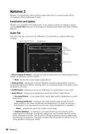
...headphones acoustic experience. ▫▫Gaming and Movies - allows you wish. ∙∙ On/Off Button - virtualizes the multichannel audio stream from MSI's official website. it maintains a constant volume for a wider sound stage. ▪▪Volume Stabilizer - Nahimic 3 Nahimic 3 is designed to ...update it, please use the Driver Disc with your multimedia experience (Music, Gaming, Movie or Communication). allows you to fit your motherboard or download the driver from the game engine or the movie soundtrack and downmixes it in one click. ∙∙ Audio ...
...headphones acoustic experience. ▫▫Gaming and Movies - allows you wish. ∙∙ On/Off Button - virtualizes the multichannel audio stream from MSI's official website. it maintains a constant volume for a wider sound stage. ▪▪Volume Stabilizer - Nahimic 3 Nahimic 3 is designed to ...update it, please use the Driver Disc with your multimedia experience (Music, Gaming, Movie or Communication). allows you to fit your motherboard or download the driver from the game engine or the movie soundtrack and downmixes it in one click. ∙∙ Audio ...


