User Manual
Page 1
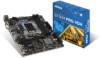
Unpacking Thank you for buying the MSI® H170M PRO-VDH/ B150M PRO-VDH/ CSM-B150M PROVDH motherboard. Check to make sure your motherboard box contains the following items. If something is missing, contact your dealer as soon as possible. Motherboard Drivers & Utilities Disc Motherboard User Guide I/O Shield SATA Cable Unpacking 1
Unpacking Thank you for buying the MSI® H170M PRO-VDH/ B150M PRO-VDH/ CSM-B150M PROVDH motherboard. Check to make sure your motherboard box contains the following items. If something is missing, contact your dealer as soon as possible. Motherboard Drivers & Utilities Disc Motherboard User Guide I/O Shield SATA Cable Unpacking 1

User Manual
Page 2
...). y Keep this user guide for future reference. y If any installation step, please consult a certified computer technician. y Store the motherboard in an environment above 60°C (140°F), it work according to avoid touching sensitive components. y All cautions and warnings on ...way that your electrical outlet provides the same voltage as injury to ensure successful computer assembly. Loose connections may damage the motherboard. 2 Safety Information y Do not boot the computer before installation is not available, discharge yourself of the following instructions to...
...). y Keep this user guide for future reference. y If any installation step, please consult a certified computer technician. y Store the motherboard in an environment above 60°C (140°F), it work according to avoid touching sensitive components. y All cautions and warnings on ...way that your electrical outlet provides the same voltage as injury to ensure successful computer assembly. Loose connections may damage the motherboard. 2 Safety Information y Do not boot the computer before installation is not available, discharge yourself of the following instructions to...

User Manual
Page 7
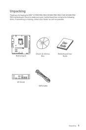
Installing the Motherboard 1 2 Quick Start 7
Installing the Motherboard 1 2 Quick Start 7

User Manual
Page 13
Contents Unpacking ...1 Safety Information 2 Quick Start ...3 Preparing Tools and Components 3 Installing a Processor 4 Installing DDR4 memory 5 Connecting the Front Panel Header 6 Installing the Motherboard 7 Installing SATA Drives 8 Installing a Graphics Card 9 Connecting Peripheral Devices 10 Connecting the Power Connectors 11 Power On...12 Specifications...15 Block Diagram ...18 Rear I/O Panel ......
Contents Unpacking ...1 Safety Information 2 Quick Start ...3 Preparing Tools and Components 3 Installing a Processor 4 Installing DDR4 memory 5 Connecting the Front Panel Header 6 Installing the Motherboard 7 Installing SATA Drives 8 Installing a Graphics Card 9 Connecting Peripheral Devices 10 Connecting the Power Connectors 11 Power On...12 Specifications...15 Block Diagram ...18 Rear I/O Panel ......

User Manual
Page 23
... of thermal paste (or thermal tape) between the CPU and the heatsink to enhance heat dissipation. MSI will deal with Return Merchandise Authorization (RMA) requests if only the motherboard comes with the CPU before installing or removing the CPU. A CPU heatsink is necessary to the ... overclocking. Always make sure that the CPU heatsink has formed a tight seal with the protective cap on the CPU socket. y This motherboard is not recommended. Overview of Components 23 The golden triangle is not installed, always protect the CPU socket pins by inadequate operation beyond product...
... of thermal paste (or thermal tape) between the CPU and the heatsink to enhance heat dissipation. MSI will deal with Return Merchandise Authorization (RMA) requests if only the motherboard comes with the CPU before installing or removing the CPU. A CPU heatsink is necessary to the ... overclocking. Always make sure that the CPU heatsink has formed a tight seal with the protective cap on the CPU socket. y This motherboard is not recommended. Overview of Components 23 The golden triangle is not installed, always protect the CPU socket pins by inadequate operation beyond product...

User Manual
Page 24
... less for full DIMMs installation or overclocking. Therefore, we recommended that the maximum capacity of memory will be a little less than 4GB memory on the motherboard. y Please note that you to install 64-bit Windows OS if you want to install more efficient memory cooling system for 32-bit Windows OS...
... less for full DIMMs installation or overclocking. Therefore, we recommended that the maximum capacity of memory will be a little less than 4GB memory on the motherboard. y Please note that you to install 64-bit Windows OS if you want to install more efficient memory cooling system for 32-bit Windows OS...

User Manual
Page 25
... devices. SATA1 SATA2 SATAe1 Important y Please do not fold the SATA or SATAe cable at a 90-degree angle. The SATAe connector can connect to the motherboard for any necessary additional hardware or software changes. Read the expansion card's documentation to check for space saving purposes. SATA1~6: SATA 6Gb/s Connectors These connectors...
... devices. SATA1 SATA2 SATAe1 Important y Please do not fold the SATA or SATAe cable at a 90-degree angle. The SATAe connector can connect to the motherboard for any necessary additional hardware or software changes. Read the expansion card's documentation to check for space saving purposes. SATA1~6: SATA 6Gb/s Connectors These connectors...

User Manual
Page 26
... - 4 5 Reset Switch 6 7 Reset Switch 8 9 Reserved 10 Power LED + Power LED Power Switch Power Switch No Pin 1 JFP2 1 Speaker - 2 3 Buzzer - 4 Buzzer + Speaker + 26 Overview of the motherboard.
... - 4 5 Reset Switch 6 7 Reset Switch 8 9 Reserved 10 Power LED + Power LED Power Switch Power Switch No Pin 1 JFP2 1 Speaker - 2 3 Buzzer - 4 Buzzer + Speaker + 26 Overview of the motherboard.

User Manual
Page 30
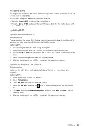
... to clear the system configuration, set the jumpers to save system configuration data. Power off your computer back into the outlet and power on the motherboard to clear the CMOS memory. Keep Data (default) Clear CMOS/ Reset BIOS Resetting BIOS to clear CMOS. 3. Plug your computer and unplug it from JBAT1...
... to clear the system configuration, set the jumpers to save system configuration data. Power off your computer back into the outlet and power on the motherboard to clear the CMOS memory. Keep Data (default) Clear CMOS/ Reset BIOS Resetting BIOS to clear CMOS. 3. Plug your computer and unplug it from JBAT1...

User Manual
Page 31
... displayed on screen when the computer is not detected or fail. Set Chassis Intrusion to BIOS > Settings > Security > Chassis Intrusion Configuration. 2. DRAM - Overview of the motherboard. Normal (default) Trigger the chassis intrusion event Using chassis intrusion detector 1. Close the chassis cover. 3. indicates DRAM is not detected or fail. Press F10 to...
... displayed on screen when the computer is not detected or fail. Set Chassis Intrusion to BIOS > Settings > Security > Chassis Intrusion Configuration. 2. DRAM - Overview of the motherboard. Normal (default) Trigger the chassis intrusion event Using chassis intrusion detector 1. Close the chassis cover. 3. indicates DRAM is not detected or fail. Press F10 to...
User Manual
Page 33
Updating BIOS: 1. Select Manual scan. 3. Select the MB BIOS and click on the motherboard. y Short the Clear CMOS jumper on icon to reboot the system and enter the flash mode. 4. Press Del key to start updating BIOS. 6. And then ... download and install the latest BIOS file. 5. BIOS Setup 33 Install and launch MSI LIVE UPDATE 6. 2. Insert the USB flash drive that matches your motherboard model from MSI website. y Press the Clear CMOS button, on the rear I/O panel. (Only for the motherboard with clear CMOS button.) Updating BIOS Updating BIOS with Live Update 6 Before...
Updating BIOS: 1. Select Manual scan. 3. Select the MB BIOS and click on the motherboard. y Short the Clear CMOS jumper on icon to reboot the system and enter the flash mode. 4. Press Del key to start updating BIOS. 6. And then ... download and install the latest BIOS file. 5. BIOS Setup 33 Install and launch MSI LIVE UPDATE 6. 2. Insert the USB flash drive that matches your motherboard model from MSI website. y Press the Clear CMOS button, on the rear I/O panel. (Only for the motherboard with clear CMOS button.) Updating BIOS Updating BIOS with Live Update 6 Before...

User Manual
Page 36
... MONITOR - provides the information of EZ Mode section. the following options are available: ƒ SETTINGS - allows you to the information of installed devices on this motherboard. provides BIOS setting items and information to update BIOS with a USB flash drive. ƒ OC PROFILE - allows you to specify the parameters for chipset and...
... MONITOR - provides the information of EZ Mode section. the following options are available: ƒ SETTINGS - allows you to the information of installed devices on this motherboard. provides BIOS setting items and information to update BIOS with a USB flash drive. ƒ OC PROFILE - allows you to specify the parameters for chipset and...

User Manual
Page 37
..., turn off computer and re-check SATA cable and power cable connections of connected SATA device. f SATA PortX Shows the information of the device and motherboard. Press to Sat, determined by users. SETTINGS System Status f System Date Sets the system date. through Dec. Advanced f PCI Subsystem Settings Sets PCI, PCI express...
..., turn off computer and re-check SATA cable and power cable connections of connected SATA device. f SATA PortX Shows the information of the device and motherboard. Press to Sat, determined by users. SETTINGS System Status f System Date Sets the system date. through Dec. Advanced f PCI Subsystem Settings Sets PCI, PCI express...

User Manual
Page 52
Insert the USB flash drive that matches your motherboard model from MSI website, save the BIOS file into the computer. 2. The system will enter the flash mode and a file selection menu will be prompted. Click on M-FLASH ...
Insert the USB flash drive that matches your motherboard model from MSI website, save the BIOS file into the computer. 2. The system will enter the flash mode and a file selection menu will be prompted. Click on M-FLASH ...

User Manual
Page 54
... temperature, system temperature and fans' speeds. In this field, drag the color buttons to keep it with a specific operating speed. f Fan control field This motherboard provides a fan speed control feature call Smart Fan. f Voltage display Shows the current voltages of CPU for four level.
... temperature, system temperature and fans' speeds. In this field, drag the color buttons to keep it with a specific operating speed. f Fan control field This motherboard provides a fan speed control feature call Smart Fan. f Voltage display Shows the current voltages of CPU for four level.

User Manual
Page 58
.... contains fields of voltage, fan speed and temperature for you to monitor the status of CPU and chipset. When system detects the status over your motherboard temperature and fan speed with date and time. ƒ To make a history record: Select items and click the Record button. y DRAM - If you want to...
.... contains fields of voltage, fan speed and temperature for you to monitor the status of CPU and chipset. When system detects the status over your motherboard temperature and fan speed with date and time. ƒ To make a history record: Select items and click the Record button. y DRAM - If you want to...

User Manual
Page 59
... on the Mobile Control control panel. Software Description 59 Download and install MSI® COMMAND CENTER APP to verify that monitoring and OC functions are working properly. Information When click the Information button, The Motherboard, CPU, Memory and HW monitor icons will slide out. 2. is... only available for the motherboard with the SSID. 6. It allows you to the instruction on the Gadget mode, a configuration panel will appear. Enable COMMAND CENTER Remote Server on the MSI® COMMAND CENTER APP to your mobile device. 7. Please ...
... on the Mobile Control control panel. Software Description 59 Download and install MSI® COMMAND CENTER APP to verify that monitoring and OC functions are working properly. Information When click the Information button, The Motherboard, CPU, Memory and HW monitor icons will slide out. 2. is... only available for the motherboard with the SSID. 6. It allows you to the instruction on the Gadget mode, a configuration panel will appear. Enable COMMAND CENTER Remote Server on the MSI® COMMAND CENTER APP to your mobile device. 7. Please ...

User Manual
Page 60
...drivers, BIOS and utilities. Select the Live Update tab. 60 Software Description shows the downloading history. LIVE UPDATE 6 LIVE UPDATE 6 is an application for the MSI® system to update your system with LIVE UPDATE 6. You can also read the relevant information by clicking the information icon on websites, and don... Live update tab at the top. y System Information - You can click the tab to know the models of the system. displays the information of motherboard and graphics cards. y Live Update - y Setting - Please follow the steps below: 1 2 4 5 3 1.
...drivers, BIOS and utilities. Select the Live Update tab. 60 Software Description shows the downloading history. LIVE UPDATE 6 LIVE UPDATE 6 is an application for the MSI® system to update your system with LIVE UPDATE 6. You can also read the relevant information by clicking the information icon on websites, and don... Live update tab at the top. y System Information - You can click the tab to know the models of the system. displays the information of motherboard and graphics cards. y Live Update - y Setting - Please follow the steps below: 1 2 4 5 3 1.

User Manual
Page 63
.../drive/download/ Dropbox: https://www.dropbox.com/downloading/ Software Description 63 Setting up Soft AP (optional) The Soft AP function is only available for the motherboard with the Soft AP function. Cloud Storage Server Detection File Transfer If you haven't installed either Google Drive or Dropbox software yet, you should check...
.../drive/download/ Dropbox: https://www.dropbox.com/downloading/ Software Description 63 Setting up Soft AP (optional) The Soft AP function is only available for the motherboard with the Soft AP function. Cloud Storage Server Detection File Transfer If you haven't installed either Google Drive or Dropbox software yet, you should check...

User Manual
Page 74
... power is turned on. y If 3 long beeps are heard, remove all memory modules and try to go over troubleshooting guide first to the motherboard? y Verify if the network cable is no signal to monitor y Connect the monitor power cord to bootup the system (Only for RMA repair...Use the secondary BIOS to a electrical outlet securely. y Connect the speakers/headphones to JFP1 pin header properly. y Select different inputs on the motherboard rear IO panel. y Test with another known working y Make sure your got similar symptoms as mentioned below. There is turned on the...
... power is turned on. y If 3 long beeps are heard, remove all memory modules and try to go over troubleshooting guide first to the motherboard? y Verify if the network cable is no signal to monitor y Connect the monitor power cord to bootup the system (Only for RMA repair...Use the secondary BIOS to a electrical outlet securely. y Connect the speakers/headphones to JFP1 pin header properly. y Select different inputs on the motherboard rear IO panel. y Test with another known working y Make sure your got similar symptoms as mentioned below. There is turned on the...


