
User Manual
Page 13
... Start ...3 Preparing Tools and Components 3 Installing a Processor 4 Installing DDR4 memory 5 Connecting the Front Panel Header 6 Installing the Motherboard 7 Installing SATA Drives 8 Installing a Graphics Card 9 Connecting Peripheral Devices 10 Connecting the Power Connectors 11 Power On...12 Specifications...15 Block Diagram ...18 Rear I/O Panel ...19 LAN Port LED Status Table 19 Realtek HD Audio Manager 19 Overview of Components 21 CPU Socket ...23 DIMM Slots...24 PCI_E1~3: PCIe Expansion Slots 25 SATA1~6: SATA 6Gb/s Connectors 25 SE1_21: SATAe Connector 25 JPWR1~2: Power...
... Start ...3 Preparing Tools and Components 3 Installing a Processor 4 Installing DDR4 memory 5 Connecting the Front Panel Header 6 Installing the Motherboard 7 Installing SATA Drives 8 Installing a Graphics Card 9 Connecting Peripheral Devices 10 Connecting the Power Connectors 11 Power On...12 Specifications...15 Block Diagram ...18 Rear I/O Panel ...19 LAN Port LED Status Table 19 Realtek HD Audio Manager 19 Overview of Components 21 CPU Socket ...23 DIMM Slots...24 PCI_E1~3: PCIe Expansion Slots 25 SATA1~6: SATA 6Gb/s Connectors 25 SE1_21: SATAe Connector 25 JPWR1~2: Power...

User Manual
Page 14
BIOS Setup ...32 Entering BIOS Setup 32 Resetting BIOS...33 Updating BIOS...33 EZ Mode ...34 Advanced Mode ...36 SETTINGS...37 Advanced...37 Boot...43 Security ...44 Save & Exit...45 OC...46 M-FLASH ...52 OC PROFILE ...53 HARDWARE MONITOR 54 Software Description 55 Installing Windows® 7/ 8.1/ 10 55 Installing Drivers 55 Installing Utilities 55 COMMAND CENTER 56 LIVE UPDATE 6...60 M-CLOUD ...62 RAMDISK...65 NETWORK GENIE 66 Intel® Extreme Tuning Utility 68 RAID Configuration (optional 69 Using Intel®...
BIOS Setup ...32 Entering BIOS Setup 32 Resetting BIOS...33 Updating BIOS...33 EZ Mode ...34 Advanced Mode ...36 SETTINGS...37 Advanced...37 Boot...43 Security ...44 Save & Exit...45 OC...46 M-FLASH ...52 OC PROFILE ...53 HARDWARE MONITOR 54 Software Description 55 Installing Windows® 7/ 8.1/ 10 55 Installing Drivers 55 Installing Utilities 55 COMMAND CENTER 56 LIVE UPDATE 6...60 M-CLOUD ...62 RAMDISK...65 NETWORK GENIE 66 Intel® Extreme Tuning Utility 68 RAID Configuration (optional 69 Using Intel®...
User Manual
Page 15
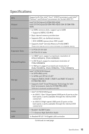
...131; 6x USB 2.0 (High-speed USB) ports (2 ports on the back panel, 4 ports available through the internal USB connectors) y Realtek® ALC887 Codec y 7.1-Channel High Definition Audio 1x Realtek RTL8111H Gigabit LAN controller Continued on compatible memory. Specifications CPU Chipset Memory Expansion Slots Onboard Graphics Storage USB Audio LAN Supports 6th Gen Intel® Core™ i3/i5/i7 processors, and Intel® Pentium® and Celeron® processors for Socket LGA1151 Intel® H170 Chipset (H170M PRO-VDH) Intel® B150 Chipset (B150M PRO-VDH/ CSM-B150M PROVDH) y 4x...
...131; 6x USB 2.0 (High-speed USB) ports (2 ports on the back panel, 4 ports available through the internal USB connectors) y Realtek® ALC887 Codec y 7.1-Channel High Definition Audio 1x Realtek RTL8111H Gigabit LAN controller Continued on compatible memory. Specifications CPU Chipset Memory Expansion Slots Onboard Graphics Storage USB Audio LAN Supports 6th Gen Intel® Core™ i3/i5/i7 processors, and Intel® Pentium® and Celeron® processors for Socket LGA1151 Intel® H170 Chipset (H170M PRO-VDH) Intel® B150 Chipset (B150M PRO-VDH/ CSM-B150M PROVDH) y 4x...
User Manual
Page 17
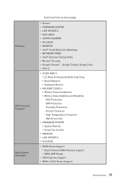
..., Google Drive y CPU-Z y CLICK BIOS 5 ƒ EZ Mode & Advanced Mode Switching ƒ Board Explorer ƒ Hardware Monitor y MILITARY CLASS 4 ƒ Military Class Component ƒ Military Class Stability and Reliability ˜ ESD Protection ˜ EMI Protection ˜ Humidity Protection ˜ Circuit Protection ˜ High Temperature Protection ˜ VGA Armor Slot y COMMAND CENTER ƒ System Monitor ƒ Smart Fan Control y RAMDISK y LIVE UPDATE 6 y M-CLOUD y DDR4 Boost Support ƒ Dual-Channel DDR4 Memory Support ƒ...
..., Google Drive y CPU-Z y CLICK BIOS 5 ƒ EZ Mode & Advanced Mode Switching ƒ Board Explorer ƒ Hardware Monitor y MILITARY CLASS 4 ƒ Military Class Component ƒ Military Class Stability and Reliability ˜ ESD Protection ˜ EMI Protection ˜ Humidity Protection ˜ Circuit Protection ˜ High Temperature Protection ˜ VGA Armor Slot y COMMAND CENTER ƒ System Monitor ƒ Smart Fan Control y RAMDISK y LIVE UPDATE 6 y M-CLOUD y DDR4 Boost Support ƒ Dual-Channel DDR4 Memory Support ƒ...

User Manual
Page 29
..., when you to adjust fan speed in relation to CPU temperature. The other is to go to use COMMAND CENTER application. CPUFAN1,SYSFAN1~2: Fan Connectors Fan connectors can be noisy. Voltage Mode fan connectors control fan speed by changing voltage. One is to BIOS > HARDWARE MONITOR. PWM Mode fan connector 1 CPUFAN1 1 Ground 2 3 Sense 4 Voltage Mode fan connector +12V Speed Control Signal 1 SYSFAN1/ SYSFAN2 1 Ground 2 Voltage Control 3 Sense 4 NC Controlling the fan speed There are two ways to a PWM Mode fan connector, the fan speed will be always maintained at...
..., when you to adjust fan speed in relation to CPU temperature. The other is to go to use COMMAND CENTER application. CPUFAN1,SYSFAN1~2: Fan Connectors Fan connectors can be noisy. Voltage Mode fan connectors control fan speed by changing voltage. One is to BIOS > HARDWARE MONITOR. PWM Mode fan connector 1 CPUFAN1 1 Ground 2 3 Sense 4 Voltage Mode fan connector +12V Speed Control Signal 1 SYSFAN1/ SYSFAN2 1 Ground 2 Voltage Control 3 Sense 4 NC Controlling the fan speed There are two ways to a PWM Mode fan connector, the fan speed will be always maintained at...

User Manual
Page 30
Keep Data (default) Clear CMOS/ Reset BIOS Resetting BIOS to clear CMOS. 3. Remove the jumper cap from the outlet. 2. JLPT1: Parallel Port Connector This connector allows you want to clear the system configuration, set the jumpers to clear the CMOS memory. Power off your computer back into the outlet and power on the motherboard to connect the optional parallel port with bracket. 2 26 1 25 1 RSTB# 2 AFD# 3 PRND0 4 ERR# 5 PRND1 6 PINIT# 7 PRND2 8 LPT_SLIN# 9 PRND3 10 Ground 11 PRND4 12...
Keep Data (default) Clear CMOS/ Reset BIOS Resetting BIOS to clear CMOS. 3. Remove the jumper cap from the outlet. 2. JLPT1: Parallel Port Connector This connector allows you want to clear the system configuration, set the jumpers to clear the CMOS memory. Power off your computer back into the outlet and power on the motherboard to connect the optional parallel port with bracket. 2 26 1 25 1 RSTB# 2 AFD# 3 PRND0 4 ERR# 5 PRND1 6 PINIT# 7 PRND2 8 LPT_SLIN# 9 PRND3 10 Ground 11 PRND4 12...
User Manual
Page 33
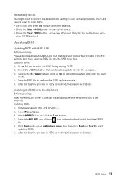
.... Install and launch MSI LIVE UPDATE 6. 2. Insert the USB flash drive that matches your motherboard model from MSI website. Click Next and choose In Windows mode. y Short the Clear CMOS jumper on Yes to download and install the latest BIOS file. 5. Updating BIOS: 1. Updating the BIOS with M-FLASH Before updating: Please download the latest BIOS file that contains the update file into the USB flash drive. Select Manual scan. 3. And then click Next and Start to load optimized defaults. Check MB BIOS box and click on Scan button. 4. After...
.... Install and launch MSI LIVE UPDATE 6. 2. Insert the USB flash drive that matches your motherboard model from MSI website. Click Next and choose In Windows mode. y Short the Clear CMOS jumper on Yes to download and install the latest BIOS file. 5. Updating BIOS: 1. Updating the BIOS with M-FLASH Before updating: Please download the latest BIOS file that contains the update file into the USB flash drive. Select Manual scan. 3. And then click Next and Start to load optimized defaults. Check MB BIOS box and click on Scan button. 4. After...
User Manual
Page 34
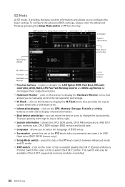
... manually control the fan speed by pressing the Setup Mode switch or F7 function key. y Language - y Screenshot - press this button to display the Hardware Monitor menu that provides the way to update BIOS with a USB flash drive. click on their respective button. This switch will only be available if the X.M.P. enable or disable the LAN Option ROM, Fast Boot, HD audio controller, AHCI, RAID, CPU Fan Fail Warning Control and BIOS Log Review by clicking on the inner circle to display related information. y Boot device priority bar - supported memory...
... manually control the fan speed by pressing the Setup Mode switch or F7 function key. y Language - y Screenshot - press this button to display the Hardware Monitor menu that provides the way to update BIOS with a USB flash drive. click on their respective button. This switch will only be available if the X.M.P. enable or disable the LAN Option ROM, Fast Boot, HD audio controller, AHCI, RAID, CPU Fan Fail Warning Control and BIOS Log Review by clicking on the inner circle to display related information. y Boot device priority bar - supported memory...
User Manual
Page 38
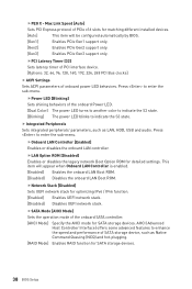
...-plugging. [RAID Mode] Enables RAID function for detailed settings. fLAN Option ROM [Disabled] Enables or disables the legacy network Boot Option ROM for SATA storage devices. 38 BIOS Setup fOnboard LAN Controller [Enabled] Enables or disables the onboard LAN controller. Press to enter the sub-menu. Press to enter the sub-menu. Max Link Speed [Auto] Sets PCI Express protocol of SATA storage device, such as LAN, HDD, USB and audio. fPEG X - fPCI Latency Timer [32] Sets latency timer of PCI interface device. [Options: 32, 64, 96, 128, 160, 192, 224, 248 PCI Bus clocks] f ACPI...
...-plugging. [RAID Mode] Enables RAID function for detailed settings. fLAN Option ROM [Disabled] Enables or disables the legacy network Boot Option ROM for SATA storage devices. 38 BIOS Setup fOnboard LAN Controller [Enabled] Enables or disables the onboard LAN controller. Press to enter the sub-menu. Press to enter the sub-menu. Max Link Speed [Auto] Sets PCI Express protocol of SATA storage device, such as LAN, HDD, USB and audio. fPEG X - fPCI Latency Timer [32] Sets latency timer of PCI interface device. [Options: 32, 64, 96, 128, 160, 192, 224, 248 PCI Bus clocks] f ACPI...

User Manual
Page 39
... [Disabled] Disables hot plug support for the SATA ports. fUSB Controller [Enabled] Enables or disables all USB controller. f USB Configuration Sets the onboard USB controller and device function. fInitiate Graphic Adapter [PEG] Selects a graphics device as the primary boot device. [IGD] Integrated Graphics Display. [PEG] PCI-Express Graphics Device. This item will appear when IGD Multi-Monitor is enabled. BIOS Setup 39 f Integrated Graphics Configuration Adjusts integrated graphics settings for SATAe PCIe device. fSATAx Hot Plug [Disabled] Allows user...
... [Disabled] Disables hot plug support for the SATA ports. fUSB Controller [Enabled] Enables or disables all USB controller. f USB Configuration Sets the onboard USB controller and device function. fInitiate Graphic Adapter [PEG] Selects a graphics device as the primary boot device. [IGD] Integrated Graphics Display. [PEG] PCI-Express Graphics Device. This item will appear when IGD Multi-Monitor is enabled. BIOS Setup 39 f Integrated Graphics Configuration Adjusts integrated graphics settings for SATAe PCIe device. fSATAx Hot Plug [Disabled] Allows user...
User Manual
Page 41
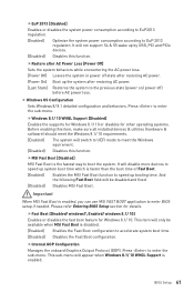
... AC power. [Power On] Boot up by USB, PCI and PCIe devices. [Disabled] Disables this function. Please refer Entering BIOS Setup section for Windows 8.1/ 10. This sub-menu will disable more devices to speed up system boot time which is enabled. It will appear when Windows 8.1/ 10 WHQL Support is faster than the boot time of Fast Boot. [Enabled] Enables the MSI Fast Boot function to speed up booting time. fInternal GOP Configuration Manages the onboard Graphics Output Protocol (GOP). f Windows OS Configuration Sets Windows 8/ 8.1 detailed...
... AC power. [Power On] Boot up by USB, PCI and PCIe devices. [Disabled] Disables this function. Please refer Entering BIOS Setup section for Windows 8.1/ 10. This sub-menu will disable more devices to speed up system boot time which is enabled. It will appear when Windows 8.1/ 10 WHQL Support is faster than the boot time of Fast Boot. [Enabled] Enables the MSI Fast Boot function to speed up booting time. fInternal GOP Configuration Manages the onboard Graphics Output Protocol (GOP). f Windows OS Configuration Sets Windows 8/ 8.1 detailed...

User Manual
Page 43
... S3/ S4/ S5 state when activity of hot key on PS/2 keyboard is detected. [Hot Key] Enables the system to be awakened from sleep state when activity of PS/2 mouse is detected. [Disabled] Disables this function. Boot Sets the sequence of the ethernet controller parameter. f Full Screen Logo Display [Enabled] Enables or disables to wake the system. BIOS Setup 43 This item appears when you to lock or...
... S3/ S4/ S5 state when activity of hot key on PS/2 keyboard is detected. [Hot Key] Enables the system to be awakened from sleep state when activity of PS/2 mouse is detected. [Disabled] Disables this function. Boot Sets the sequence of the ethernet controller parameter. f Full Screen Logo Display [Enabled] Enables or disables to wake the system. BIOS Setup 43 This item appears when you to lock or...

User Manual
Page 44
f FIXED BOOT ORDER Priorities Sets device priority for accessing the system. The password typed now will replace any previous set . You may also press to enter the sub-menu. 44 BIOS Setup f Trusted Computing Sets TPM (Trusted Platform Module) function. f Chassis Intrusion Configuration Press to abort the selection. f Boot Mode Select [LEGACY+UEFI] Sets the system boot mode from CMOS memory. Once the password is being disabled. fSecurity Device Support [Enabled] Enables or disables the TPM function to change the BIOS items. This item...
f FIXED BOOT ORDER Priorities Sets device priority for accessing the system. The password typed now will replace any previous set . You may also press to enter the sub-menu. 44 BIOS Setup f Trusted Computing Sets TPM (Trusted Platform Module) function. f Chassis Intrusion Configuration Press to abort the selection. f Boot Mode Select [LEGACY+UEFI] Sets the system boot mode from CMOS memory. Once the password is being disabled. fSecurity Device Support [Enabled] Enables or disables the TPM function to change the BIOS items. This item...
User Manual
Page 47
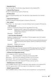
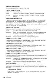
... the overclocking behavior is installed. BIOS Setup 47 Read-only. f DRAM Frequency [Auto] Sets the DRAM frequency. f GT Ratio [Auto] Sets the integrated graphics ratio. Read-only. fEIST [Enabled]* Enables or disables the Enhanced Intel® SpeedStep Technology. [Enabled] Enables the EIST to CPU features. f DRAM Reference Clock [Auto]* Sets the DRAM reference clock. f Misc Setting* Press Enter, + or - Please note that support this adjustment is not guaranteed. key to open or close the following 3 items related to adjust CPU voltage and core frequency...
... the overclocking behavior is installed. BIOS Setup 47 Read-only. f DRAM Frequency [Auto] Sets the DRAM frequency. f GT Ratio [Auto] Sets the integrated graphics ratio. Read-only. fEIST [Enabled]* Enables or disables the Enhanced Intel® SpeedStep Technology. [Enabled] Enables the EIST to CPU features. f DRAM Reference Clock [Auto]* Sets the DRAM reference clock. f Misc Setting* Press Enter, + or - Please note that support this adjustment is not guaranteed. key to open or close the following 3 items related to adjust CPU voltage and core frequency...
User Manual
Page 48
... load the default settings.) f Memory Fast Boot [Auto] * Enables or disables the initiation and training for each/ all memory channel. [UnLink] Allows user to enter the sub-menu. This sub-menu displays the information of installed CPU. Read only. 48 BIOS Setup f CPU Specifications Press to enter the sub-menu. You can set the voltages related to CPU. fCPU Technology Support Press to enter the sub-menu. The system may become unstable or unbootable after changing memory timing. f CPU Memory Changed Detect [Enabled]* Enables...
... load the default settings.) f Memory Fast Boot [Auto] * Enables or disables the initiation and training for each/ all memory channel. [UnLink] Allows user to enter the sub-menu. This sub-menu displays the information of installed CPU. Read only. 48 BIOS Setup f CPU Specifications Press to enter the sub-menu. You can set the voltages related to CPU. fCPU Technology Support Press to enter the sub-menu. The system may become unstable or unbootable after changing memory timing. f CPU Memory Changed Detect [Enabled]* Enables...

User Manual
Page 50
... AES Instructions [Enabled] Enables or disables the CPU AES (Advanced Encryption Standard-New Instructions) support. C-state is idle. fC1E Support [Disabled] Enables or disables the C1E function for power-saving when system is a processor power management technology defined by ACPI. [Auto] This setting will be configured automatically by BIOS. [C0~C8] The power-saving level from overheating. [Enabled] Throttles down the CPU core clock speed when the CPU is C8 to low is over the adaptive temperature. [Disabled] Disables this...
... AES Instructions [Enabled] Enables or disables the CPU AES (Advanced Encryption Standard-New Instructions) support. C-state is idle. fC1E Support [Disabled] Enables or disables the C1E function for power-saving when system is a processor power management technology defined by ACPI. [Auto] This setting will be configured automatically by BIOS. [C0~C8] The power-saving level from overheating. [Enabled] Throttles down the CPU core clock speed when the CPU is C8 to low is over the adaptive temperature. [Disabled] Disables this...

User Manual
Page 52
... motherboard model from MSI website, save the BIOS file into the computer. 2. Click on Yes to update BIOS. 1. Click on M-FLASH tab, a demand message will reboot automatically. 52 BIOS Setup M-FLASH M-FLASH provides the way to perform the BIOS update process. 5. Select a BIOS file to update BIOS with a USB flash drive. Insert the USB flash drive that matches your USB flash drive. After the flashing process is 100% completed, the system will be prompted. The system will enter the flash mode...
... motherboard model from MSI website, save the BIOS file into the computer. 2. Click on Yes to update BIOS. 1. Click on M-FLASH tab, a demand message will reboot automatically. 52 BIOS Setup M-FLASH M-FLASH provides the way to perform the BIOS update process. 5. Select a BIOS file to update BIOS with a USB flash drive. Insert the USB flash drive that matches your USB flash drive. After the flashing process is 100% completed, the system will be prompted. The system will enter the flash mode...

User Manual
Page 55
.... 5. Power on the screen to boot from the Boot Menu. 7. For windows 8.1/ 10, skip this step. Press any key when screen shows Press any key to install Windows® 7/ 8.1/ 10. Start up your optical drive. 2. Restart your optical drive. 3. Insert the Windows® 7/ 8.1/ 10 disc into Boot Menu. 6. The utilities installation will find and list all necessary drivers. 4. Click Install button. 5. Installing Utilities Before you install utilities, you want to restart. 7. For Windows 7, access the BIOS menu SETTING > Advanced > Windows OS Configuration > Windows...
.... 5. Power on the screen to boot from the Boot Menu. 7. For windows 8.1/ 10, skip this step. Press any key when screen shows Press any key to install Windows® 7/ 8.1/ 10. Start up your optical drive. 2. Restart your optical drive. 3. Insert the Windows® 7/ 8.1/ 10 disc into Boot Menu. 6. The utilities installation will find and list all necessary drivers. 4. Click Install button. 5. Installing Utilities Before you install utilities, you want to restart. 7. For Windows 7, access the BIOS menu SETTING > Advanced > Windows OS Configuration > Windows...

User Manual
Page 74
... troubleshooting guide first to see if your USB drive driver has been installed. The power is listed in Windows® Device Manager. y If 3 long beeps are heard, remove and reinstall the graphics card and then restart the computer. y Test with another known working graphics card. There is connected from the power supply to the motherboard? Lost BIOS password y Clear the CMOS, but no network y Make sure the network chipset driver has been installed. y Restart or reset your TCP/IP settings. y Check if all ATX power connectors...
... troubleshooting guide first to see if your USB drive driver has been installed. The power is listed in Windows® Device Manager. y If 3 long beeps are heard, remove and reinstall the graphics card and then restart the computer. y Test with another known working graphics card. There is connected from the power supply to the motherboard? Lost BIOS password y Clear the CMOS, but no network y Make sure the network chipset driver has been installed. y Restart or reset your TCP/IP settings. y Check if all ATX power connectors...
User Manual
Page 78
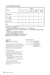
.../07, For H170M PRO-DH/ B150M PRO-DH. The material in this document is given as to make changes without notice. Technical Support If a problem arises with your product at: http://register.msi.com Trademark Recognition All product names used in this manual are the properties of Micro-Star Int'l Co.,Ltd. Version 1.1, 2015/07, For H170M PRO-VDH/ B150M PRO-VDH. 部件名...
.../07, For H170M PRO-DH/ B150M PRO-DH. The material in this document is given as to make changes without notice. Technical Support If a problem arises with your product at: http://register.msi.com Trademark Recognition All product names used in this manual are the properties of Micro-Star Int'l Co.,Ltd. Version 1.1, 2015/07, For H170M PRO-VDH/ B150M PRO-VDH. 部件名...


