User Guide
Page 1
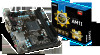
English English Thank you for choosing the AM1I Series (MS-7865 v2.X) Mini-ITX motherboard. The AM1I Series motherboards are designed to fit the advanced AMD AM1 processor, the AM1I Series motherboards deliver a high performance and professional desktop platform solution. Out B:Mic-In JAUD1 JBAT1 JTPM1 MINI_PCIE_1 JFP1 SATA1 SATA2 PCI_E1 JCOM1 DIMM1 DIMM2 SYSFAN1 11 Layout T: mouse B:keyboard JPWR1 CPUFAN1 HDMI port BUZ1 JPWR2 T: VGA B: DVI-D JCI1 JUSB2 USB3.0 ports JUSB1 T: LAN Jack B: USB2.0 ports T:Line-In M:Line-
English English Thank you for choosing the AM1I Series (MS-7865 v2.X) Mini-ITX motherboard. The AM1I Series motherboards are designed to fit the advanced AMD AM1 processor, the AM1I Series motherboards deliver a high performance and professional desktop platform solution. Out B:Mic-In JAUD1 JBAT1 JTPM1 MINI_PCIE_1 JFP1 SATA1 SATA2 PCI_E1 JCOM1 DIMM1 DIMM2 SYSFAN1 11 Layout T: mouse B:keyboard JPWR1 CPUFAN1 HDMI port BUZ1 JPWR2 T: VGA B: DVI-D JCI1 JUSB2 USB3.0 ports JUSB1 T: LAN Jack B: USB2.0 ports T:Line-In M:Line-
User Guide
Page 2
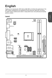
English Motherboard Specifications Processor Memory Support Expansion Slots Onboard Graphics Storage USB 3.0 USB 2.0 Audio LAN Back Panel Connectors Internal Connectors ■ AMD Socket AM1 Processors ■ 2x ...
English Motherboard Specifications Processor Memory Support Expansion Slots Onboard Graphics Storage USB 3.0 USB 2.0 Audio LAN Back Panel Connectors Internal Connectors ■ AMD Socket AM1 Processors ■ 2x ...
User Guide
Page 5
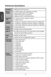
... and maintain system stability. http://youtu.be seen. The APU can damage both the APU and the motherboard. An APU heatsink is properly and completely embedded into the socket and close the lever with your motherboard. 4. Look for the gold arrow of the correct installation procedures may cause permanent damages to your...
... and maintain system stability. http://youtu.be seen. The APU can damage both the APU and the motherboard. An APU heatsink is properly and completely embedded into the socket and close the lever with your motherboard. 4. Look for the gold arrow of the correct installation procedures may cause permanent damages to your...
User Guide
Page 6
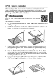
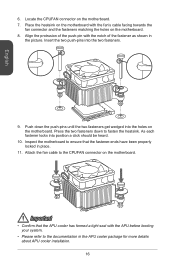
... refer to the documentation in the APU cooler package for more details about APU cooler installation. 16 Push down to the CPUFAN connector on the motherboard. English 6. Align the protrusion of the fastener as shown in place. 11. Important • Confirm that the fastener-ends have been properly locked ...in the picture. Press the two fasteners down the push-pins until the two fasteners get wedged into the holes on the motherboard. Place the heatsink on the motherboard with the fan's cable facing towards the fan connector and the fasteners matching the holes on the...
... refer to the documentation in the APU cooler package for more details about APU cooler installation. 16 Push down to the CPUFAN connector on the motherboard. English 6. Align the protrusion of the fastener as shown in place. 11. Important • Confirm that the fastener-ends have been properly locked ...in the picture. Press the two fasteners down the push-pins until the two fasteners get wedged into the holes on the motherboard. Place the heatsink on the motherboard with the fan's cable facing towards the fan connector and the fasteners matching the holes on the...
User Guide
Page 8
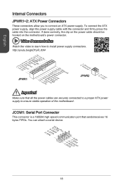
...high speed communication port that all the power cables are securely connected to a proper ATX power supply to ensure stable operation of the motherboard. http://youtu.be hooked on the power cable should be /gkDYyR_83I4 1.+2J3.+3.P33.G4VW.3.r+5VoR.5uG6Vn1.r7+do.5uG8Vn.rP9do.Wu51nV0R1d.S1+...Internal Connectors JPWR1~2: ATX Power Connectors These connectors allow you to install power supply connectors. If done correctly, the clip on the motherboard's power connector. To connect the ATX power supply, align the power supply cable with the connector and firmly press the cable into the...
...high speed communication port that all the power cables are securely connected to a proper ATX power supply to ensure stable operation of the motherboard. http://youtu.be hooked on the power cable should be /gkDYyR_83I4 1.+2J3.+3.P33.G4VW.3.r+5VoR.5uG6Vn1.r7+do.5uG8Vn.rP9do.Wu51nV0R1d.S1+...Internal Connectors JPWR1~2: ATX Power Connectors These connectors allow you to install power supply connectors. If done correctly, the clip on the motherboard's power connector. To connect the ATX power supply, align the power supply cable with the connector and firmly press the cable into the...
User Guide
Page 9
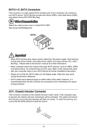
... SATA1~2: SATA Connectors This connector is opened, the chassis intrusion mechanism will flash on either sides of the cable. Each connector can connect to the motherboard for further installation instructions. • Please do not fold the SATA cable at a 90-degree angle. Data loss may result during transmission otherwise. • SATA...
... SATA1~2: SATA Connectors This connector is opened, the chassis intrusion mechanism will flash on either sides of the cable. Each connector can connect to the motherboard for further installation instructions. • Please do not fold the SATA cable at a 90-degree angle. Data loss may result during transmission otherwise. • SATA...
User Guide
Page 10
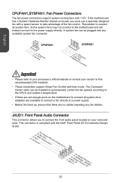
Some system fans may not connect to the motherboard and will instead connect to find recommended CPU heatsink. • These connectors support Smart Fan Control with a speed sensor to connect the front audio panel ... Important • Please refer to your processor's official website or consult your computer case. This connector is compliant with +12V. If the motherboard has a System Hardware Monitor chipset on the motherboard to a power supply. • Before first boot up, ensure that there are no cables impeding any available system fan connector. The...
Some system fans may not connect to the motherboard and will instead connect to find recommended CPU heatsink. • These connectors support Smart Fan Control with a speed sensor to connect the front audio panel ... Important • Please refer to your processor's official website or consult your computer case. This connector is compliant with +12V. If the motherboard has a System Hardware Monitor chipset on the motherboard to a power supply. • Before first boot up, ensure that there are no cables impeding any available system fan connector. The...
User Guide
Page 11
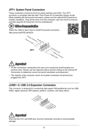
... connectors connect to determine correct connector orientation and placement. • The majority of the computer case's front panel connectors will primarily be plugged into the motherboard. Plug all the wires from the case, pins marked by small triangles are positive wires. Please use the optional M-Connector to simplify installation. JUSB1~2: USB...
... connectors connect to determine correct connector orientation and placement. • The majority of the computer case's front panel connectors will primarily be plugged into the motherboard. Plug all the wires from the case, pins marked by small triangles are positive wires. Please use the optional M-Connector to simplify installation. JUSB1~2: USB...
User Guide
Page 12
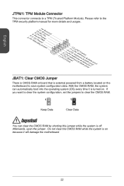
... to clear the CMOS RAM. 1 1 Keep Data Clear Data Important You can automatically boot into the operating system (OS) every time it is on the motherboard to save system configuration data. With the CMOS RAM, the system can clear the CMOS RAM by shorting this jumper while the system is off...&sraraedt&amsasdpteaa&intpa0dinap1tian2pin3 JBAT1: Clear CMOS Jumper There is CMOS RAM onboard that is external powered from a battery located on because it will damage the motherboard. 22
... to clear the CMOS RAM. 1 1 Keep Data Clear Data Important You can automatically boot into the operating system (OS) every time it is on the motherboard to save system configuration data. With the CMOS RAM, the system can clear the CMOS RAM by shorting this jumper while the system is off...&sraraedt&amsasdpteaa&intpa0dinap1tian2pin3 JBAT1: Clear CMOS Jumper There is CMOS RAM onboard that is external powered from a battery located on because it will damage the motherboard. 22


