User Guide
Page 1
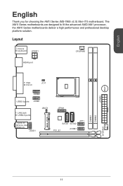
Out B:Mic-In JAUD1 JBAT1 JTPM1 MINI_PCIE_1 JFP1 SATA1 SATA2 PCI_E1 JCOM1 DIMM1 DIMM2 SYSFAN1 11 The AM1I Series motherboards are designed to fit the advanced AMD AM1 processor, the AM1I Series motherboards deliver a high performance and professional desktop platform solution. Layout T: mouse B:keyboard JPWR1 CPUFAN1 HDMI port BUZ1 JPWR2 T: VGA B: DVI-D JCI1 JUSB2 USB3.0 ports JUSB1 T: LAN Jack B: USB2.0 ports T:Line-In M:Line- English English Thank you for choosing the AM1I Series (MS-7865 v2.X) Mini-ITX motherboard.
Out B:Mic-In JAUD1 JBAT1 JTPM1 MINI_PCIE_1 JFP1 SATA1 SATA2 PCI_E1 JCOM1 DIMM1 DIMM2 SYSFAN1 11 The AM1I Series motherboards are designed to fit the advanced AMD AM1 processor, the AM1I Series motherboards deliver a high performance and professional desktop platform solution. Layout T: mouse B:keyboard JPWR1 CPUFAN1 HDMI port BUZ1 JPWR2 T: VGA B: DVI-D JCI1 JUSB2 USB3.0 ports JUSB1 T: LAN Jack B: USB2.0 ports T:Line-In M:Line- English English Thank you for choosing the AM1I Series (MS-7865 v2.X) Mini-ITX motherboard.
User Guide
Page 2
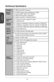
...; 1x DVI-D port ■ 1x HDMI port ■ 2x USB 3.0 ports ■ 2x USB 2.0 ports ■ 1x LAN (RJ45) port ■ 3x audio jacks ■ 1x 24-pin ATX main power connector ■ 1x 4-pin ATX 12V power connector ■ 2x SATA 6Gb/s connectors ■ 2x USB 2.0 connectors (supports additional 4 USB 2.0 ports) ■ 1x 3-pin CPU fan connector ■ 1x 4-pin system fan connector ■ 1x Front panel audio connector ■ 1x Serial port connector ■ 1x TPM connector ■ 1x System panel connector ■ 1x Chassis Intrusion connector ■ 1x Clear CMOS jumper 12
...; 1x DVI-D port ■ 1x HDMI port ■ 2x USB 3.0 ports ■ 2x USB 2.0 ports ■ 1x LAN (RJ45) port ■ 3x audio jacks ■ 1x 24-pin ATX main power connector ■ 1x 4-pin ATX 12V power connector ■ 2x SATA 6Gb/s connectors ■ 2x USB 2.0 connectors (supports additional 4 USB 2.0 ports) ■ 1x 3-pin CPU fan connector ■ 1x 4-pin system fan connector ■ 1x Front panel audio connector ■ 1x Serial port connector ■ 1x TPM connector ■ 1x System panel connector ■ 1x Chassis Intrusion connector ■ 1x Clear CMOS jumper 12

User Guide
Page 3
x 6.7 in . English BIOS Features ■ UEFI AMI BIOS ■ ACPI 5.0, PnP 1.0a, SM BIOS 2.7, DMI 2.0 ■ Multi-language Form Factor ■ Mini-ITX Form Factor ■ 6.7 in . (17.0 cm x 17.0 cm) For the latest information about CPU, please visit http://www.msi.com/service/cpu-support/ For more information on compatible components, please visit http://www.msi.com/service/test-report/ 13
x 6.7 in . English BIOS Features ■ UEFI AMI BIOS ■ ACPI 5.0, PnP 1.0a, SM BIOS 2.7, DMI 2.0 ■ Multi-language Form Factor ■ Mini-ITX Form Factor ■ 6.7 in . (17.0 cm x 17.0 cm) For the latest information about CPU, please visit http://www.msi.com/service/cpu-support/ For more information on compatible components, please visit http://www.msi.com/service/test-report/ 13
User Guide
Page 4
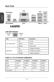
English Back Panel PS/2 Mouse VGA HDMI PS/2 Keyboard DVI-D ® LAN USB 3.0 USB 2.0 Audio LAN LED Indicator LINK/ACT LED SPEED LED LED Link/ Activity LED Speed LED LED Status Off Yellow Blinking Off Green Orange Description No link Linked Data activity 10 Mbps connection 100 Mbps connection 1 Gbps connection Audio 2, 4, 6 or 8-channel configuration Port Blue Green Pink Front audio 2-channel Line in Line out Mic - 4-channel RS-Out FS-Out Mic - 6-channel RS-Out FS-Out CS-Out - 8-channel RS-Out FS-Out CS-Out SS-Out 14
English Back Panel PS/2 Mouse VGA HDMI PS/2 Keyboard DVI-D ® LAN USB 3.0 USB 2.0 Audio LAN LED Indicator LINK/ACT LED SPEED LED LED Link/ Activity LED Speed LED LED Status Off Yellow Blinking Off Green Orange Description No link Linked Data activity 10 Mbps connection 100 Mbps connection 1 Gbps connection Audio 2, 4, 6 or 8-channel configuration Port Blue Green Pink Front audio 2-channel Line in Line out Mic - 4-channel RS-Out FS-Out Mic - 6-channel RS-Out FS-Out CS-Out - 8-channel RS-Out FS-Out CS-Out SS-Out 14
User Guide
Page 5
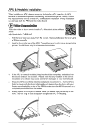
...Follow the steps below to install APU & heatsink at the address below. Video Demonstration Watch the video to learn how to ensure correct APU and heatsink installation. If the APU is properly and completely embedded into the socket. 5. Press the APU down firmly into the socket and can not be /s--...correctly installed, the pins should point as shown in heat dissipation and prevent APU overheating. 15 Look for the gold arrow of the correct installation procedures may cause permanent damages to a 90-degree angle. 2. The APU can damage both the APU and the motherboard. ...
...Follow the steps below to install APU & heatsink at the address below. Video Demonstration Watch the video to learn how to ensure correct APU and heatsink installation. If the APU is properly and completely embedded into the socket. 5. Press the APU down firmly into the socket and can not be /s--...correctly installed, the pins should point as shown in heat dissipation and prevent APU overheating. 15 Look for the gold arrow of the correct installation procedures may cause permanent damages to a 90-degree angle. 2. The APU can damage both the APU and the motherboard. ...
User Guide
Page 6
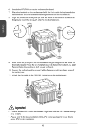
Attach the fan cable to fasten the heatsink. English 6. Place the heatsink on the motherboard with the notch of the push-pin with the fan's cable facing towards the fan connector and the fasteners matching the holes on the motherboard. Push down to the CPUFAN connector on the motherboard. 7. Insert the two push-pins into the holes on the motherboard. 8. Inspect the motherboard to the documentation in...
Attach the fan cable to fasten the heatsink. English 6. Place the heatsink on the motherboard with the notch of the push-pin with the fan's cable facing towards the fan connector and the fasteners matching the holes on the motherboard. Push down to the CPUFAN connector on the motherboard. 7. Insert the two push-pins into the holes on the motherboard. 8. Inspect the motherboard to the documentation in...

User Guide
Page 7
.... http://youtu.be/76yLtJaKlCQ Important • DDR3 memory modules are used for installing memory modules. English Memory These DIMM slots are not interchangeable with DDR2, and the DDR3 standard is not backward compatible. For more information on compatible components, please visit http://www.msi.com/service/test-report/ DIMM1 DIMM2 Video Demonstration Watch the video to learn how to 31+ GB of...
.... http://youtu.be/76yLtJaKlCQ Important • DDR3 memory modules are used for installing memory modules. English Memory These DIMM slots are not interchangeable with DDR2, and the DDR3 standard is not backward compatible. For more information on compatible components, please visit http://www.msi.com/service/test-report/ DIMM1 DIMM2 Video Demonstration Watch the video to learn how to 31+ GB of...
User Guide
Page 8
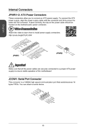
... a serial device. 2.S4I.ND6T.DR8S1.C0RT.NSo Pin 1.D3.CS5DO.G7Ur.RTo9uT.RnSdI 18 JCOM1: Serial Port Connector This connector is a 16550A high speed communication port that all the power cables are securely connected to a proper ATX power supply to install power supply connectors. Video Demonstration Watch the video to learn how to ensure stable operation of the motherboard. To connect the ATX power supply, align the power supply cable with the connector and firmly press the cable into the connector. English Internal Connectors JPWR1~2: ATX Power Connectors...
... a serial device. 2.S4I.ND6T.DR8S1.C0RT.NSo Pin 1.D3.CS5DO.G7Ur.RTo9uT.RnSdI 18 JCOM1: Serial Port Connector This connector is a 16550A high speed communication port that all the power cables are securely connected to a proper ATX power supply to install power supply connectors. Video Demonstration Watch the video to learn how to ensure stable operation of the motherboard. To connect the ATX power supply, align the power supply cable with the connector and firmly press the cable into the connector. English Internal Connectors JPWR1~2: ATX Power Connectors...
User Guide
Page 9
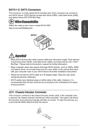
... clear the warning, you must enter the BIOS utility and clear the record. 2.C1.IGNTroRuUnd 19 SATA devices include disk drives (HDD), solid state drives (SSD), and optical drives (CD/ DVD/ Blu-Ray). Data loss may result during transmission otherwise. • SATA cables have identical plugs on screen. Each connector can connect to the chassis intrusion switch cable. Video Demonstration Watch the video to learn how to the device's manual for further information. • Many computer cases...
... clear the warning, you must enter the BIOS utility and clear the record. 2.C1.IGNTroRuUnd 19 SATA devices include disk drives (HDD), solid state drives (SSD), and optical drives (CD/ DVD/ Blu-Ray). Data loss may result during transmission otherwise. • SATA cables have identical plugs on screen. Each connector can connect to the chassis intrusion switch cable. Video Demonstration Watch the video to learn how to the device's manual for further information. • Many computer cases...
User Guide
Page 10
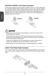
... utility can be installed to automatically control the fan speeds according to the CPU's and system's temperature. • If there are not enough ports on -board, you to find recommended CPU heatsink. • These connectors support Smart Fan Control with a speed sensor to a power supply. • Before first boot up, ensure that there are available to connect a fan directly to take advantage of the fan control. If the motherboard has a System Hardware Monitor chipset on the motherboard to connect...
... utility can be installed to automatically control the fan speeds according to the CPU's and system's temperature. • If there are not enough ports on -board, you to find recommended CPU heatsink. • These connectors support Smart Fan Control with a speed sensor to a power supply. • Before first boot up, ensure that there are available to connect a fan directly to take advantage of the fan control. If the motherboard has a System Hardware Monitor chipset on the motherboard to connect...
User Guide
Page 11
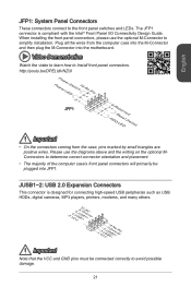
... VCC and GND pins must be plugged into the motherboard. When installing the front panel connectors, please use the diagrams above and the writing on the optional MConnectors to determine correct connector orientation and placement. • The majority of the computer case's front panel connectors will primarily be connected correctly to simplify installation. Video Demonstration Watch the video to learn how to the front panel switches and LEDs. http://youtu...
... VCC and GND pins must be plugged into the motherboard. When installing the front panel connectors, please use the diagrams above and the writing on the optional MConnectors to determine correct connector orientation and placement. • The majority of the computer case's front panel connectors will primarily be connected correctly to simplify installation. Video Demonstration Watch the video to learn how to the front panel switches and LEDs. http://youtu...
User Guide
Page 12
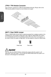
... CMOS RAM, the system can clear the CMOS RAM by shorting this jumper while the system is external powered from a battery located on . If you want to clear the system configuration, set the jumpers to a TPM (Trusted Platform Module). English JTPM1: TPM Module Connector This connector connects to clear the CMOS RAM. 1 1 Keep Data Clear Data Important You can automatically boot into the operating system (OS) every time it will damage the motherboard...
... CMOS RAM, the system can clear the CMOS RAM by shorting this jumper while the system is external powered from a battery located on . If you want to clear the system configuration, set the jumpers to a TPM (Trusted Platform Module). English JTPM1: TPM Module Connector This connector connects to clear the CMOS RAM. 1 1 Keep Data Clear Data Important You can automatically boot into the operating system (OS) every time it will damage the motherboard...
User Guide
Page 13
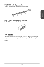
Important When adding or removing expansion cards, always turn off the power supply and unplug the power supply power cable from the power outlet. MINI_PCI_E1: Mini-PCIe Expansion Slot The Mini-PCIe slot supports the Mini-PCIe interface expansion card. Read the expansion card's documentation to check for any necessary additional hardware or software changes. 23 English PCI_E1: PCIe x16 Expansion Slot The PCIe slot supports the PCIe interface expansion card.
Important When adding or removing expansion cards, always turn off the power supply and unplug the power supply power cable from the power outlet. MINI_PCI_E1: Mini-PCIe Expansion Slot The Mini-PCIe slot supports the Mini-PCIe interface expansion card. Read the expansion card's documentation to check for any necessary additional hardware or software changes. 23 English PCI_E1: PCIe x16 Expansion Slot The PCIe slot supports the PCIe interface expansion card.

User Guide
Page 14
...; Please load the default settings to USB Exit 24 When the message below appears on the screen during the system booting up, and requests you to run the Setup program when: ■ An error message appears on the screen, press key to enter BIOS: Press DEL key to enter Setup Menu, F11 to enter Boot Menu If the message disappears before you respond and you keep the default settings to avoid...
...; Please load the default settings to USB Exit 24 When the message below appears on the screen during the system booting up, and requests you to run the Setup program when: ■ An error message appears on the screen, press key to enter BIOS: Press DEL key to enter Setup Menu, F11 to enter Boot Menu If the message disappears before you respond and you keep the default settings to avoid...
User Guide
Page 15
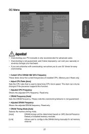
... adjusted DRAM frequency. Read-only. ▶ DRAM Timing Mode [Auto] Selects the memory timing mode. [Auto] DRAM timings will be changed if the processor supports this function. ▶ Adjusted CPU Frequency Shows the adjusted CPU frequency. Read-only. ▶ Adjust CPU Ratio [Auto] Sets the CPU ratio that is used to configure the DRAM timing manually for easy overclocking. ▶ Current CPU/ DRAM/ NB/ GPU Frequency These items show the current frequencies of installed memory modules. [Link] Allows user to determine CPU clock speed. OC Menu...
... adjusted DRAM frequency. Read-only. ▶ DRAM Timing Mode [Auto] Selects the memory timing mode. [Auto] DRAM timings will be changed if the processor supports this function. ▶ Adjusted CPU Frequency Shows the adjusted CPU frequency. Read-only. ▶ Adjust CPU Ratio [Auto] Sets the CPU ratio that is used to configure the DRAM timing manually for easy overclocking. ▶ Current CPU/ DRAM/ NB/ GPU Frequency These items show the current frequencies of installed memory modules. [Link] Allows user to determine CPU clock speed. OC Menu...

User Guide
Page 16
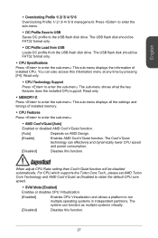
... modulating clock generator pulses. [Enabled] Enables the spread spectrum function to enter the sub-menu. If it manually. ▶ CPU Memory Changed Detect [Enabled] Enables or disables the system to issue a warning message during boot when the CPU or memory has been replaced. [Enabled] The system will issue a warning message during boot and than needs to load the default settings for respective memory channel. ▶ Advanced DRAM Configuration Press to reduce the EMI (Electromagnetic Interference) problem. [Disabled...
... modulating clock generator pulses. [Enabled] Enables the spread spectrum function to enter the sub-menu. If it manually. ▶ CPU Memory Changed Detect [Enabled] Enables or disables the system to issue a warning message during boot when the CPU or memory has been replaced. [Enabled] The system will issue a warning message during boot and than needs to load the default settings for respective memory channel. ▶ Advanced DRAM Configuration Press to reduce the EMI (Electromagnetic Interference) problem. [Disabled...
User Guide
Page 17
... Disabled to retain the default CPU core speed. ▶ SVM Mode [Enabled] Enables or disables CPU Virtualization. [Enabled] Enables CPU Virtualization and allows a platform to enter the sub-menu. Read only. ▶ CPU Technology Support Press to enter the sub-menu. You can effectively and dynamically lower CPU speed and power consumption. [Disabled] Disables this function. 27 This sub-menu displays the information of installed memory. ▶ CPU Features Press to the USB flash disk drive. Read only. ▶ MEMORY-Z Press to enter the sub-menu. The USB flash disk...
... Disabled to retain the default CPU core speed. ▶ SVM Mode [Enabled] Enables or disables CPU Virtualization. [Enabled] Enables CPU Virtualization and allows a platform to enter the sub-menu. Read only. ▶ CPU Technology Support Press to enter the sub-menu. You can effectively and dynamically lower CPU speed and power consumption. [Disabled] Disables this function. 27 This sub-menu displays the information of installed memory. ▶ CPU Features Press to the USB flash disk drive. Read only. ▶ MEMORY-Z Press to enter the sub-menu. The USB flash disk...
User Guide
Page 18
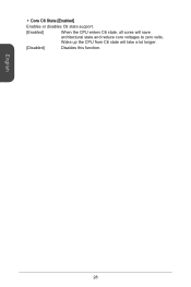
▶ Core C6 State [Enabled] Enables or disables C6 state support. [Enabled] When the CPU enters C6 state, all cores will take a lot longer. [Disabled] Disables this function. English 28 Wake up the CPU from C6 state will save architectural state and reduce core voltages to zero volts.
▶ Core C6 State [Enabled] Enables or disables C6 state support. [Enabled] When the CPU enters C6 state, all cores will take a lot longer. [Disabled] Disables this function. English 28 Wake up the CPU from C6 state will save architectural state and reduce core voltages to zero volts.

