User Guide
Page 2
...and nForce are registered trademarks of International Business Machines Corporation. Alternatively, please try the following help resources for FAQ, technical guide, BIOS updates, driver updates, and other countries. Netware® is a registered trademark of American Megatrends Inc. Revision History Revision V1.0 ... Award® is the intellectual property of purchase or local distributor. Visit the MSI website for further guidance. func=faqIndex Contact our technical staff at: http://support.msi.com.tw/ ii We take every care in the United States and/or other...
...and nForce are registered trademarks of International Business Machines Corporation. Alternatively, please try the following help resources for FAQ, technical guide, BIOS updates, driver updates, and other countries. Netware® is a registered trademark of American Megatrends Inc. Revision History Revision V1.0 ... Award® is the intellectual property of purchase or local distributor. Visit the MSI website for further guidance. func=faqIndex Contact our technical staff at: http://support.msi.com.tw/ ii We take every care in the United States and/or other...
User Guide
Page 8
...Memory ...2-7 Power Supply ...2-8 Back Panel ...2-9 Connectors ...2-11 Jumpers ...2-18 Slots ...2-19 Chapter 3 BIOS Setup 3-1 Entering Setup ...3-2 The Main Menu ...3-4 Standard CMOS Features 3-6 Advanced BIOS Features 3-9 Integrated Peripherals 3-11 Power Management Setup 3-13 PNP/PCI Configurations 3-15 H/W Monitor ......3-17 Cell Menu ...3-18 Load Fail-Safe/ Optimized Defaults 3-21 BIOS Setting Password 3-22 Appendix A Dual Core Center A-1 Activating Dual Core Center A-2 Main ...A-3 DOT (Dynamic OverClocking A-5 Clock...
...Memory ...2-7 Power Supply ...2-8 Back Panel ...2-9 Connectors ...2-11 Jumpers ...2-18 Slots ...2-19 Chapter 3 BIOS Setup 3-1 Entering Setup ...3-2 The Main Menu ...3-4 Standard CMOS Features 3-6 Advanced BIOS Features 3-9 Integrated Peripherals 3-11 Power Management Setup 3-13 PNP/PCI Configurations 3-15 H/W Monitor ......3-17 Cell Menu ...3-18 Load Fail-Safe/ Optimized Defaults 3-21 BIOS Setting Password 3-22 Appendix A Dual Core Center A-1 Activating Dual Core Center A-2 Main ...A-3 DOT (Dynamic OverClocking A-5 Clock...

User Guide
Page 9
FAN Speed ...A-8 Temperature ...A-9 User Profile ...A-10 Appendix B Intel ICH7R SATA RAID B-1 ICH7R Introduction B-2 BIOS Configuration B-3 Installing Software B-9 RAID Migration Instructions B-15 Degraded RAID Array B-22 ix
FAN Speed ...A-8 Temperature ...A-9 User Profile ...A-10 Appendix B Intel ICH7R SATA RAID B-1 ICH7R Introduction B-2 BIOS Configuration B-3 Installing Software B-9 RAID Migration Instructions B-15 Degraded RAID Array B-22 ix
User Guide
Page 20
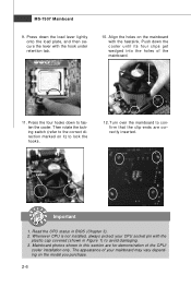
... CPU socket pin with the hook under retention tab. 10. Align the holes on the model you purchase. 2-6 locking switch Important 1. Mainboard photos shown in BIOS (Chapter 3). 2. Press the four hooks down to confirm that the clip-ends are for demonstration of the mainboard. 11. Turn over the mainboard to fasten...
... CPU socket pin with the hook under retention tab. 10. Align the holes on the model you purchase. 2-6 locking switch Important 1. Mainboard photos shown in BIOS (Chapter 3). 2. Press the four hooks down to confirm that the clip-ends are for demonstration of the mainboard. 11. Turn over the mainboard to fasten...
User Guide
Page 28
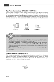
...a specially designed fan with speed sensor to the +12V; the black wire is the positive and should be connected to take advantage of BIOS and install Dual Core Center utility that the red wire is Ground and should be connected to the recommended CPU fans at processor's official website... or consult the vendors for CPUFAN. To clear the warning, you must enter the BIOS utility and clear the record. You can adjust fan speed in H/W Monitor menu of the CPU fan control. Chassis Intrusion Connector: JCI1 This ...
...a specially designed fan with speed sensor to the +12V; the black wire is the positive and should be connected to take advantage of BIOS and install Dual Core Center utility that the red wire is Ground and should be connected to the recommended CPU fans at processor's official website... or consult the vendors for CPUFAN. To clear the warning, you must enter the BIOS utility and clear the record. You can adjust fan speed in H/W Monitor menu of the CPU fan control. Chassis Intrusion Connector: JCI1 This ...
User Guide
Page 34
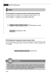
..., and other add-on cards that you unplug the power supply first. Meanwhile, read the documentation for the expansion card, such as jumpers, switches or BIOS configuration. 2-20 The PCI Express x 16 supports up to 250 MB/s transfer rate. The PCI Express x 1 supports up to configure any necessary hardware or software...
..., and other add-on cards that you unplug the power supply first. Meanwhile, read the documentation for the expansion card, such as jumpers, switches or BIOS configuration. 2-20 The PCI Express x 16 supports up to 250 MB/s transfer rate. The PCI Express x 1 supports up to configure any necessary hardware or software...
User Guide
Page 36
Chapter 3 BIOS Setup BIOS Setup This chapter provides information on the screen during the system booting up, and requests you to change the default settings for optimum use. You may need to run the Setup program when: ² An error message appears on the BIOS Setup program and allows you to run SETUP. ² You want to configure the system for customized features. 3-1
Chapter 3 BIOS Setup BIOS Setup This chapter provides information on the screen during the system booting up, and requests you to change the default settings for optimum use. You may need to run the Setup program when: ² An error message appears on the BIOS Setup program and allows you to run SETUP. ² You want to configure the system for customized features. 3-1
User Guide
Page 37
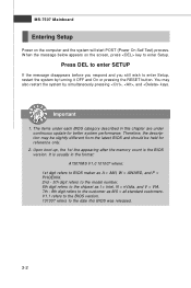
... If the message disappears before you respond and you still wish to the date this chapter are under each BIOS category described in the format: A7507IMS V1.0 101007 where: 1st digit refers to BIOS maker as A = AMI, W = AWARD, and P = PHOENIX. 2nd - 5th digit refers to the model ...up, the 1st line appearing after the memory count is usually in this BIOS was released. 3-2 You may be slightly different from the latest BIOS and should be held for better system performance. It is the BIOS version. Important 1. Therefore, the description may also restart the system by turning...
... If the message disappears before you respond and you still wish to the date this chapter are under each BIOS category described in the format: A7507IMS V1.0 101007 where: 1st digit refers to BIOS maker as A = AMI, W = AWARD, and P = PHOENIX. 2nd - 5th digit refers to the model ...up, the 1st line appearing after the memory count is usually in this BIOS was released. 3-2 You may be slightly different from the latest BIOS and should be held for better system performance. It is the BIOS version. Important 1. Therefore, the description may also restart the system by turning...
User Guide
Page 38
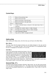
BIOS Setup Control Keys Enter> Move to the previous item Move to the next item Move to the item in the left hand Move to the ... enter values and move from any menu by simply pressing . If you can use the control keys to exit the Help screen. 3-3 General Help The BIOS setup program provides a General Help screen. The on-line description of the highlighted setup function is the Main Menu. You can make changes Load Optimized...
BIOS Setup Control Keys Enter> Move to the previous item Move to the next item Move to the item in the left hand Move to the ... enter values and move from any menu by simply pressing . If you can use the control keys to exit the Help screen. 3-3 General Help The BIOS setup program provides a General Help screen. The on-line description of the highlighted setup function is the Main Menu. You can make changes Load Optimized...
User Guide
Page 39
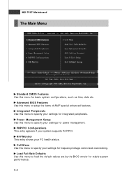
... menu to specify your settings for stable system performance. 3-4 Integrated Peripherals Use this menu to specify your settings for integrated peripherals. Advanced BIOS Features Use this menu for basic system configurations, such as time, date etc. Load Fail-Safe Defaults Use this menu to specify your... settings for frequency/voltage control and overclocking. Power Management Setup Use this menu to load the default values set by the BIOS vendor for power management. MS-7507 Mainboard The Main Menu Standard CMOS Features Use this menu to setup the items of AMI®...
... menu to specify your settings for stable system performance. 3-4 Integrated Peripherals Use this menu to specify your settings for integrated peripherals. Advanced BIOS Features Use this menu for basic system configurations, such as time, date etc. Load Fail-Safe Defaults Use this menu to specify your... settings for frequency/voltage control and overclocking. Power Management Setup Use this menu to load the default values set by the BIOS vendor for power management. MS-7507 Mainboard The Main Menu Standard CMOS Features Use this menu to setup the items of AMI®...
User Guide
Page 40
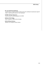
Exit Without Saving Abandon all changes and exit setup. 3-5 BIOS Setup Load Optimized Defaults Use this menu to load the default values set the password for optimal performance of the mainboard. BIOS Setting Password Use this menu to set by the mainboard manufacturer specifically for BIOS. Save & Exit Setup Save changes to CMOS and exit setup.
Exit Without Saving Abandon all changes and exit setup. 3-5 BIOS Setup Load Optimized Defaults Use this menu to load the default values set the password for optimal performance of the mainboard. BIOS Setting Password Use this menu to set by the mainboard manufacturer specifically for BIOS. Save & Exit Setup Save changes to CMOS and exit setup.
User Guide
Page 41
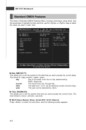
... to the date that you want in each item. day Day of the week, from Jan. month The month from Sun to Sat, determined by BIOS. through Dec. year The year can be adjusted by numeric function keys. Read-only. IDE Primary Master/ Slave, Serial-ATA 1/2/3/4 Channel Press to enter the...
... to the date that you want in each item. day Day of the week, from Jan. month The month from Sun to Sat, determined by BIOS. through Dec. year The year can be adjusted by numeric function keys. Read-only. IDE Primary Master/ Slave, Serial-ATA 1/2/3/4 Channel Press to enter the...
User Guide
Page 42
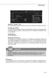
Hard Disk S.M.A.R.T. Available options: [None], [360K, 5.25 in.], [1.2M, 5.25 in.], [720K, 3.5 in.], [1.44M, 3.5 in.], [2.88M, 3.5 in.]. 3-7 This allows you to the SATA connector. BIOS Setup Device / Vender / Size It will showing the device information that you connected to activate the S.M.A.R.T. (Self-Monitoring Analysis & Reporting Technology) capability for the hard ...
Hard Disk S.M.A.R.T. Available options: [None], [360K, 5.25 in.], [1.2M, 5.25 in.], [720K, 3.5 in.], [1.44M, 3.5 in.], [2.88M, 3.5 in.]. 3-7 This allows you to the SATA connector. BIOS Setup Device / Vender / Size It will showing the device information that you connected to activate the S.M.A.R.T. (Self-Monitoring Analysis & Reporting Technology) capability for the hard ...
User Guide
Page 43
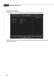
MS-7507 Mainboard System Information Press to enter the sub-menu, and the following screen appears. This sub-menu shows the CPU information, BIOS version and memory status of your system (read only). 3-8
MS-7507 Mainboard System Information Press to enter the sub-menu, and the following screen appears. This sub-menu shows the CPU information, BIOS version and memory status of your system (read only). 3-8
User Guide
Page 44
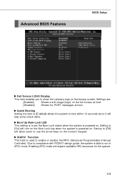
... to [Enabled] allows the system to boot within 10 seconds since it will allow users to show the company logo on the bootup screen. Advanced BIOS Features BIOS Setup Full Screen LOGO Display This item enables you to use the arrow keys on the numeric keypad.
... to [Enabled] allows the system to boot within 10 seconds since it will allow users to show the company logo on the bootup screen. Advanced BIOS Features BIOS Setup Full Screen LOGO Display This item enables you to use the arrow keys on the numeric keypad.
User Guide
Page 45
.... Boot Sequence Press to enter the sub-menu: 1st/ 2nd Boot Device The items allow you to set the first/ second/ third boot device where BIOS attempts to enter the sub-menu: Hyper-Threading Technology This field appears only when the CPU supports Hyper-Threading.
.... Boot Sequence Press to enter the sub-menu: 1st/ 2nd Boot Device The items allow you to set the first/ second/ third boot device where BIOS attempts to enter the sub-menu: Hyper-Threading Technology This field appears only when the CPU supports Hyper-Threading.

User Guide
Page 46
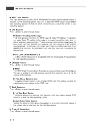
... you to enable/disable the TCG/TPM. Use the left / right arrow key to select between [OK] and [Cancel], then press to confirm your choice. BIOS Setup TCG/TPM SUPPORT This setting allows you to enable or disable the TPM security chip. TPM Enable/Disable Status This item is not configurable...
... you to enable/disable the TCG/TPM. Use the left / right arrow key to select between [OK] and [Cancel], then press to confirm your choice. BIOS Setup TCG/TPM SUPPORT This setting allows you to enable or disable the TPM security chip. TPM Enable/Disable Status This item is not configurable...
User Guide
Page 47
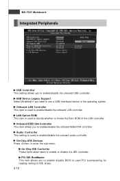
... setting is used PCI busmastering for reading/ writing to enable/disable the onboard LAN controller. Onboard IEEE1394 Controller This item allows you to enable/ disable BIOS to used to IDE drives. 3-12 PCI IDE BusMaster This item allows you to enable/disable the onboard audio controller. Onboard LAN Controller This item...
... setting is used PCI busmastering for reading/ writing to enable/disable the onboard LAN controller. Onboard IEEE1394 Controller This item allows you to enable/ disable BIOS to used to IDE drives. 3-12 PCI IDE BusMaster This item allows you to enable/disable the onboard audio controller. Onboard LAN Controller This item...
User Guide
Page 48
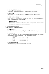
BIOS Setup On-Chip SATA Controller These items allow users to select the type of IDE devices. RAID Mode This item is a built-in parallel port ...
BIOS Setup On-Chip SATA Controller These items allow users to select the type of IDE devices. RAID Mode This item is a built-in parallel port ...
User Guide
Page 49
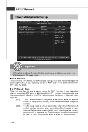
... the ACPI (Advanced Configuration and Power Management Interface) Function. MS-7507 Mainboard Power Management Setup Important S3-related functions described in this field. If your BIOS supports S3 sleep mode.
... the ACPI (Advanced Configuration and Power Management Interface) Function. MS-7507 Mainboard Power Management Setup Important S3-related functions described in this field. If your BIOS supports S3 sleep mode.


