User Guide
Page 2
... MSI website for further guidance. Our products are registered trademarks of Intel Corporation. Trademarks All trademarks are registered trademarks of AMD Corporation. Award® is a registered trademark of Novell, Inc. Alternatively, please try the following help resources for FAQ, technical guide, BIOS .../2 and OS®/2 are registered trademarks of purchase or local distributor. func=faqIndex Contact our technical staff at: http://support.msi.com.tw/ ii We take every care in the preparation of this document is a registered trademark of American Megatrends Inc. ...
... MSI website for further guidance. Our products are registered trademarks of Intel Corporation. Trademarks All trademarks are registered trademarks of AMD Corporation. Award® is a registered trademark of Novell, Inc. Alternatively, please try the following help resources for FAQ, technical guide, BIOS .../2 and OS®/2 are registered trademarks of purchase or local distributor. func=faqIndex Contact our technical staff at: http://support.msi.com.tw/ ii We take every care in the preparation of this document is a registered trademark of American Megatrends Inc. ...
User Guide
Page 8
... Setup 2-1 Quick Components Guide 2-2 CPU (Central Processing Unit 2-3 Memory ...2-7 Power Supply ...2-8 Back Panel ...2-9 Connectors ...2-11 Jumpers ...2-18 Slots ...2-19 Chapter 3 BIOS Setup 3-1 Entering Setup ...3-2 The Main Menu ...3-4 Standard CMOS Features 3-6 Advanced BIOS Features 3-9 Integrated Peripherals 3-11 Power Management Setup 3-13 PNP/PCI Configurations 3-15 H/W Monitor ...3-17 Cell Menu ...3-18 Load Fail-Safe...
... Setup 2-1 Quick Components Guide 2-2 CPU (Central Processing Unit 2-3 Memory ...2-7 Power Supply ...2-8 Back Panel ...2-9 Connectors ...2-11 Jumpers ...2-18 Slots ...2-19 Chapter 3 BIOS Setup 3-1 Entering Setup ...3-2 The Main Menu ...3-4 Standard CMOS Features 3-6 Advanced BIOS Features 3-9 Integrated Peripherals 3-11 Power Management Setup 3-13 PNP/PCI Configurations 3-15 H/W Monitor ...3-17 Cell Menu ...3-18 Load Fail-Safe...
User Guide
Page 9
FAN Speed ...A-8 Temperature ...A-9 User Profile ...A-10 Appendix B Intel ICH7R SATA RAID B-1 ICH7R Introduction B-2 BIOS Configuration B-3 Installing Software B-9 RAID Migration Instructions B-15 Degraded RAID Array B-22 ix
FAN Speed ...A-8 Temperature ...A-9 User Profile ...A-10 Appendix B Intel ICH7R SATA RAID B-1 ICH7R Introduction B-2 BIOS Configuration B-3 Installing Software B-9 RAID Migration Instructions B-15 Degraded RAID Array B-22 ix
User Guide
Page 20
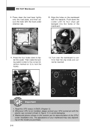
... the mainboard. 11. Press down the load lever lightly onto the load plate, and then secure the lever with the plastic cap covered (shown in BIOS (Chapter 3). 2. Turn over the mainboard to lock the h ook s . 12. Align the holes on the model you purchase. 2-6
... the mainboard. 11. Press down the load lever lightly onto the load plate, and then secure the lever with the plastic cap covered (shown in BIOS (Chapter 3). 2. Turn over the mainboard to lock the h ook s . 12. Align the holes on the model you purchase. 2-6
User Guide
Page 28
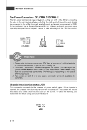
... proper CPU cooling fan. 2. If the mainboard has a System Hardware Monitor chipset on the screen. To clear the warning, you must enter the BIOS utility and clear the record. W hen connecting the wire to the connectors, always note that the red wire is opened, the chassis intrusion mechanism... will be connected to take advantage of BIOS and install Dual Core Center utility that will record this status and show a warning message on -board, you must use a specially designed fan...
... proper CPU cooling fan. 2. If the mainboard has a System Hardware Monitor chipset on the screen. To clear the warning, you must enter the BIOS utility and clear the record. W hen connecting the wire to the connectors, always note that the red wire is opened, the chassis intrusion mechanism... will be connected to take advantage of BIOS and install Dual Core Center utility that will record this status and show a warning message on -board, you must use a specially designed fan...
User Guide
Page 34
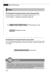
... supply first. The PCI Express x 16 supports up to configure any necessary hardware or software settings for the expansion card, such as jumpers, switches or BIOS configuration. 2-20 MS-7507 Mainboard Slots PCI (Peripheral Component Interconnect) Express Slots The PCI Express slot supports the PCI Express interface expansion card.
... supply first. The PCI Express x 16 supports up to configure any necessary hardware or software settings for the expansion card, such as jumpers, switches or BIOS configuration. 2-20 MS-7507 Mainboard Slots PCI (Peripheral Component Interconnect) Express Slots The PCI Express slot supports the PCI Express interface expansion card.
User Guide
Page 36
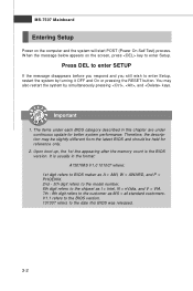
You may need to run the Setup program when: ² An error message appears on the BIOS Setup program and allows you to run SETUP. ² You want to configure the system for customized features. 3-1 Chapter 3 BIOS Setup BIOS Setup This chapter provides information on the screen during the system booting up, and requests you to change the default settings for optimum use.
You may need to run the Setup program when: ² An error message appears on the BIOS Setup program and allows you to run SETUP. ² You want to configure the system for customized features. 3-1 Chapter 3 BIOS Setup BIOS Setup This chapter provides information on the screen during the system booting up, and requests you to change the default settings for optimum use.
User Guide
Page 37
.... 101007 refers to enter Setup, restart the system by simultaneously pressing , , and keys. You may be slightly different from the latest BIOS and should be held for better system performance. The items under continuous update for reference only. 2. Press DEL to enter SETUP If the message disappears... N = nVidia, and V = VIA. 7th - 8th digit refers to enter Setup. Upon boot-up, the 1st line appearing after the memory count is usually in this BIOS was released. 3-2 Therefore, the description may also restart the system by turning it OFF and On or pressing the RESET button.
.... 101007 refers to enter Setup, restart the system by simultaneously pressing , , and keys. You may be slightly different from the latest BIOS and should be held for better system performance. The items under continuous update for reference only. 2. Press DEL to enter SETUP If the message disappears... N = nVidia, and V = VIA. 7th - 8th digit refers to enter Setup. Upon boot-up, the 1st line appearing after the memory count is usually in this BIOS was released. 3-2 Therefore, the description may also restart the system by turning it OFF and On or pressing the RESET button.
User Guide
Page 38
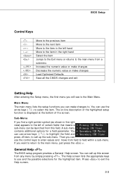
...;↓ ) to highlight the field and press to call up the sub-menu. General Help The BIOS setup program provides a General Help screen. The Help screen lists the appropriate keys to select the item. BIOS Setup Control Keys Enter> Move to the previous item Move to the next item Move to the...
...;↓ ) to highlight the field and press to call up the sub-menu. General Help The BIOS setup program provides a General Help screen. The Help screen lists the appropriate keys to select the item. BIOS Setup Control Keys Enter> Move to the previous item Move to the next item Move to the...
User Guide
Page 39
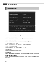
... your settings for integrated peripherals. Load Fail-Safe Defaults Use this menu to load the default values set by the BIOS vendor for basic system configurations, such as time, date etc. Advanced BIOS Features Use this menu for stable system performance. 3-4 PNP/PCI Configurations This entry appears if your PC health status...
... your settings for integrated peripherals. Load Fail-Safe Defaults Use this menu to load the default values set by the BIOS vendor for basic system configurations, such as time, date etc. Advanced BIOS Features Use this menu for stable system performance. 3-4 PNP/PCI Configurations This entry appears if your PC health status...
User Guide
Page 40
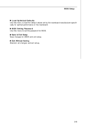
Exit Without Saving Abandon all changes and exit setup. 3-5 BIOS Setup Load Optimized Defaults Use this menu to set by the mainboard manufacturer specifically for BIOS. Save & Exit Setup Save changes to load the default values set the password for optimal performance of the mainboard. BIOS Setting Password Use this menu to CMOS and exit setup.
Exit Without Saving Abandon all changes and exit setup. 3-5 BIOS Setup Load Optimized Defaults Use this menu to set by the mainboard manufacturer specifically for BIOS. Save & Exit Setup Save changes to load the default values set the password for optimal performance of the mainboard. BIOS Setting Password Use this menu to CMOS and exit setup.
User Guide
Page 41
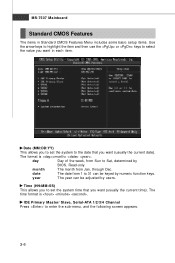
... Features Menu includes some basic setup items. Use the arrow keys to highlight the item and then use the or keys to Sat, determined by BIOS. through Dec. MS-7507 Mainboard Standard CMOS Features The items in each item. The format is . The time format is . day Day of the week...
... Features Menu includes some basic setup items. Use the arrow keys to highlight the item and then use the or keys to Sat, determined by BIOS. through Dec. MS-7507 Mainboard Standard CMOS Features The items in each item. The format is . The time format is . day Day of the week...
User Guide
Page 42
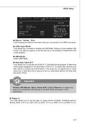
... formatted with LBA mode disabled. DM A M ode Select DMA Mode. Available options: [None], [360K, 5.25 in.], [1.2M, 5.25 in.], [720K, 3.5 in.], [1.44M, 3.5 in.], [2.88M, 3.5 in.]. 3-7 BIOS Setup Device / Vender / Size It will showing the device information that you connected to set the type of floppy drives installed. Hard Disk S.M.A.R.T. Floppy A This...
... formatted with LBA mode disabled. DM A M ode Select DMA Mode. Available options: [None], [360K, 5.25 in.], [1.2M, 5.25 in.], [720K, 3.5 in.], [1.44M, 3.5 in.], [2.88M, 3.5 in.]. 3-7 BIOS Setup Device / Vender / Size It will showing the device information that you connected to set the type of floppy drives installed. Hard Disk S.M.A.R.T. Floppy A This...
User Guide
Page 43
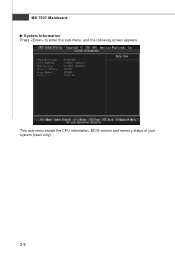
MS-7507 Mainboard System Information Press to enter the sub-menu, and the following screen appears. This sub-menu shows the CPU information, BIOS version and memory status of your system (read only). 3-8
MS-7507 Mainboard System Information Press to enter the sub-menu, and the following screen appears. This sub-menu shows the CPU information, BIOS version and memory status of your system (read only). 3-8
User Guide
Page 44
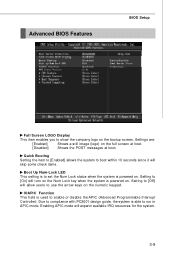
... Num Lock key when the system is used to show the company logo on . IOAPIC Function This field is powered on the bootup screen. Advanced BIOS Features BIOS Setup Full Screen LOGO Display This item enables you to enable or disable the APIC (Advanced Programmable Interrupt Controller). Setting to [Off] will skip...
... Num Lock key when the system is used to show the company logo on . IOAPIC Function This field is powered on the bootup screen. Advanced BIOS Features BIOS Setup Full Screen LOGO Display This item enables you to enable or disable the APIC (Advanced Programmable Interrupt Controller). Setting to [Off] will skip...
User Guide
Page 45
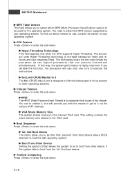
... listed speed of your operating system. If you disable the f unction, the processor will provide you to set the first/ second/ third boot device where BIOS attempts to execute the instructions. This setting controls the exact memory size shared to use only one core to load the disk operating system. To...
... listed speed of your operating system. If you disable the f unction, the processor will provide you to set the first/ second/ third boot device where BIOS attempts to execute the instructions. This setting controls the exact memory size shared to use only one core to load the disk operating system. To...

User Guide
Page 46
... the user information saved in the security chip. W hen you press , a warning message will appear to ask if you to enable/disable the TCG/TPM. BIOS Setup TCG/TPM SUPPORT This setting allows you want to clear the user information in the TPM security chip. TPM Enable/Disable Status This item...
... the user information saved in the security chip. W hen you press , a warning message will appear to ask if you to enable/disable the TCG/TPM. BIOS Setup TCG/TPM SUPPORT This setting allows you want to clear the user information in the TPM security chip. TPM Enable/Disable Status This item...
User Guide
Page 47
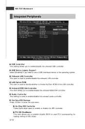
... system. PCI IDE BusMaster This item allows you to enable/disable the onboard IEEE1394 controller. Onboard IEEE1394 Controller This item allows you to enable/ disable BIOS to used to invoke the Boot ROM of the LAN controller. Audio Controller This setting is used PCI busmastering for reading/ writing to enable or...
... system. PCI IDE BusMaster This item allows you to enable/disable the onboard IEEE1394 controller. Onboard IEEE1394 Controller This item allows you to enable/ disable BIOS to used to invoke the Boot ROM of the LAN controller. Audio Controller This setting is used PCI busmastering for reading/ writing to enable or...
User Guide
Page 48
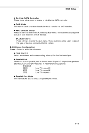
... of devices connected to the system. These submenu allow users to enable or disable the SATA controller. I /O chipset that provides Standard, ECP, and EPP features. BIOS Setup On-Chip SATA Controller These items allow users to select the type of IDE devices. RAID Mode This item is a built-in parallel port...
... of devices connected to the system. These submenu allow users to enable or disable the SATA controller. I /O chipset that provides Standard, ECP, and EPP features. BIOS Setup On-Chip SATA Controller These items allow users to select the type of IDE devices. RAID Mode This item is a built-in parallel port...
User Guide
Page 49
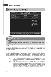
... configuration and open applications/files is saved to main memory that remains powered while most other hardware components turn off to save energy. If your BIOS supports S3 sleep mode.
... configuration and open applications/files is saved to main memory that remains powered while most other hardware components turn off to save energy. If your BIOS supports S3 sleep mode.


