User Guide
Page 9
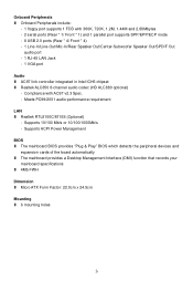
Supports ACPI Power Management BIOS l The mainboard BIOS provides "Plug & Play" BIOS which detects the peripheral devices and expansion cards of the board automatically l The mainboard provides a Desktop Management Interface (DMI) function that records your mainboard specifications l 4Mb FWH Dimension l Micro ATX Form Factor: 22.0cm x 24.5cm Mounting l 6 mounting holes 3 Supports 10/100 Mb/s or...
Supports ACPI Power Management BIOS l The mainboard BIOS provides "Plug & Play" BIOS which detects the peripheral devices and expansion cards of the board automatically l The mainboard provides a Desktop Management Interface (DMI) function that records your mainboard specifications l 4Mb FWH Dimension l Micro ATX Form Factor: 22.0cm x 24.5cm Mounting l 6 mounting holes 3 Supports 10/100 Mb/s or...
User Guide
Page 11
... the CPU, then press down the load lever lightly onto the load plate, and then secure the lever with the cooler. Check the information in BIOS for details) again and push the clip to lift up , pressing the clips on it to be installed. (For the updated supporting memory modules, ...please visit http://www.msi.com.tw/program/products/mainboard/mbd/pro_mbd_trp_list.php) 5 Align the holes on the mainboard with the hook under retention tab. 13. Turn over the mainboard...
... the CPU, then press down the load lever lightly onto the load plate, and then secure the lever with the cooler. Check the information in BIOS for details) again and push the clip to lift up , pressing the clips on it to be installed. (For the updated supporting memory modules, ...please visit http://www.msi.com.tw/program/products/mainboard/mbd/pro_mbd_trp_list.php) 5 Align the holes on the mainboard with the hook under retention tab. 13. Turn over the mainboard...
User Guide
Page 13
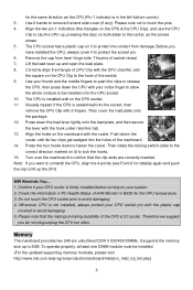
... 7 Power LED JFP2 Each Serial ATA TXN RXN GND connector can support three- or four-pin head connector. You must enter the BIOS utility and clear the record. The JFP1 is connected to GND. Each supports 1st GND generation serial ATA data rates of the CPU ...Connectors: CPUFAN1/SYSFAN1 The 4-pin CPUFAN1 (processor fan) and 3-pin SYSFAN1 (system fan) support system cooling fan with Serial ATA 1.0 specifications. MSI Reminds You... Serial Port Connector: JCOM1 The mainboard provides one serial port header for electrical connection to IrDA Infrared module and is opened, the...
... 7 Power LED JFP2 Each Serial ATA TXN RXN GND connector can support three- or four-pin head connector. You must enter the BIOS utility and clear the record. The JFP1 is connected to GND. Each supports 1st GND generation serial ATA data rates of the CPU ...Connectors: CPUFAN1/SYSFAN1 The 4-pin CPUFAN1 (processor fan) and 3-pin SYSFAN1 (system fan) support system cooling fan with Serial ATA 1.0 specifications. MSI Reminds You... Serial Port Connector: JCOM1 The mainboard provides one serial port header for electrical connection to IrDA Infrared module and is opened, the...
User Guide
Page 15
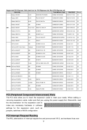
... or software settings for PCI Express Lite Slot (PCI Express x4) VGA Chip VGA Memory Type VGA BIOS Radeon X300SE ASUS EAX300SE/TD/128M/A 128MB, DDR SDRAN 008.015.117.000 Result OK Radeon X600 ...-A47401-102 OK Radeon X850XT ATI X850XT 256MB/DDR SGRAM 009.007.001.004 OK GeForce 6200 MSI MS-8981 Ver:100 128MB, DDR SDRAN 5.43.02.16.11 OK GeForce 6200 Turbo Cache Gigabyte... OK GeForce PCX5750 Leadtek Winfast PX360 TD 128MB/DDR SDRAM 4.36.20.38.00 OK GeForce PCX5750 MSI MS-8969 128MB/DDR SDRAM 4.36.20.38.12 OK GeForce PCX5900 ELSA Gladiac PCX935 128MB/DDR SGRAM...
... or software settings for PCI Express Lite Slot (PCI Express x4) VGA Chip VGA Memory Type VGA BIOS Radeon X300SE ASUS EAX300SE/TD/128M/A 128MB, DDR SDRAN 008.015.117.000 Result OK Radeon X600 ...-A47401-102 OK Radeon X850XT ATI X850XT 256MB/DDR SGRAM 009.007.001.004 OK GeForce 6200 MSI MS-8981 Ver:100 128MB, DDR SDRAN 5.43.02.16.11 OK GeForce 6200 Turbo Cache Gigabyte... OK GeForce PCX5750 Leadtek Winfast PX360 TD 128MB/DDR SDRAM 4.36.20.38.00 OK GeForce PCX5750 MSI MS-8969 128MB/DDR SDRAM 4.36.20.38.12 OK GeForce PCX5900 ELSA Gladiac PCX935 128MB/DDR SGRAM...
User Guide
Page 16
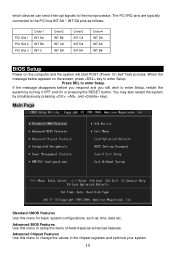
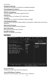
Advanced BIOS Features Use this menu to enter Setup, restart the system by simultaneously pressing , , and keys. Press DEL to enter Setup If the message disappears before ..., such as follows: PCI Slot 1 PCI Slot 2 PCI Slot 3 Order1 INT A# INT B# INT C Order2 INT B# INT C# INT D# Order3 INT C# INT D# INT A# Order4 INT D# INT A# INT B# BIOS Setup Power on the computer and the system will start POST (Power On Self Test) process. which devices can send interrupt signals to setup the...
Advanced BIOS Features Use this menu to enter Setup, restart the system by simultaneously pressing , , and keys. Press DEL to enter Setup If the message disappears before ..., such as follows: PCI Slot 1 PCI Slot 2 PCI Slot 3 Order1 INT A# INT B# INT C Order2 INT B# INT C# INT D# Order3 INT C# INT D# INT A# Order4 INT D# INT A# INT B# BIOS Setup Power on the computer and the system will start POST (Power On Self Test) process. which devices can send interrupt signals to setup the...
User Guide
Page 17
Load Optimized Defaults Use this menu to load factory default settings into the BIOS for stable system performance operations. BIOS Setting Password Use this menu to set BIOS setting Password. Exit Without Saving Abandon all changes and exit setup. Read-only. Current DDR Memory Frequency It shows the current frequency of frequency/voltage. ...
Load Optimized Defaults Use this menu to load factory default settings into the BIOS for stable system performance operations. BIOS Setting Password Use this menu to set BIOS setting Password. Exit Without Saving Abandon all changes and exit setup. Read-only. Current DDR Memory Frequency It shows the current frequency of frequency/voltage. ...
User Guide
Page 46
...;配) - 兼容 AC97 v2.3 PC99/2001 LAN l Realtek RTL8100C/8110S (选配) - 支持 10/100 Mb/s or 10/100/1000Mb/s - 支持 ACPI BIOS l 主板的 BIOS 提供了"Plug & Play l DMI l 4Mb FWH 尺寸 l Micro ATX 22.0cm x 24.5cm 固定孔 l 6 40
...;配) - 兼容 AC97 v2.3 PC99/2001 LAN l Realtek RTL8100C/8110S (选配) - 支持 10/100 Mb/s or 10/100/1000Mb/s - 支持 ACPI BIOS l 主板的 BIOS 提供了"Plug & Play l DMI l 4Mb FWH 尺寸 l Micro ATX 22.0cm x 24.5cm 固定孔 l 6 40
User Guide
Page 50
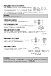
... +12V GND CPU 风扇. JCOM1 12 SIN SOUT GND DTR DSR RTS CTS IrDA JIR2 RI KEY 9 10 IrDA BIOS IR 功能.JIR1 是和 Intel 的 I/O IRTX JCASE2 2-pin BIOS 2 GND 1 CINTRU JFP1/JFP2 JFP1 是和 Intel 的 I/O 10 9 Power Switch Reset Switch Power LED HDD LED 21...
... +12V GND CPU 风扇. JCOM1 12 SIN SOUT GND DTR DSR RTS CTS IrDA JIR2 RI KEY 9 10 IrDA BIOS IR 功能.JIR1 是和 Intel 的 I/O IRTX JCASE2 2-pin BIOS 2 GND 1 CINTRU JFP1/JFP2 JFP1 是和 Intel 的 I/O 10 9 Power Switch Reset Switch Power LED HDD LED 21...
User Guide
Page 54
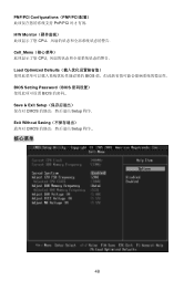
PNP/PCI Configurations(PNP/PCI PnP/PCI H/W Monitor CPU Cell_Menu CPU Load Optimized Defaults BIOS BIOS Setting Password(BIOS BIOS Save & Exit Setup CMOS Setup 程序. Exit Without Saving CMOS Setup 程序.. 核心菜单 48
PNP/PCI Configurations(PNP/PCI PnP/PCI H/W Monitor CPU Cell_Menu CPU Load Optimized Defaults BIOS BIOS Setting Password(BIOS BIOS Save & Exit Setup CMOS Setup 程序. Exit Without Saving CMOS Setup 程序.. 核心菜单 48

User Guide
Page 62
... DTR DSR CTS KEY IrDA BIOS JIR1 Intel IRTX JCASE2 2 GND 2-pin 1 CINTRU BIOS 10 9 Speaker JFP1/JFP2 LED JFP1 Intel Power Switch Power Reset Switch HDD 2 1 8 7 LED LED Power 21 LED JFP1 JFP2 JAUD1 JAUD1 Intel AUD_RET_R AUD_VCC Key (2)AUD_GND (1)AUD_MIC AUD_RET_L(10) AUD_FPOUT_L(9) AUD_MIC_BIAS HP_ON AUD_FPOUT_R MSI 5 & 6, 9 & 10 2 10 1 9 面板...
... DTR DSR CTS KEY IrDA BIOS JIR1 Intel IRTX JCASE2 2 GND 2-pin 1 CINTRU BIOS 10 9 Speaker JFP1/JFP2 LED JFP1 Intel Power Switch Power Reset Switch HDD 2 1 8 7 LED LED Power 21 LED JFP1 JFP2 JAUD1 JAUD1 Intel AUD_RET_R AUD_VCC Key (2)AUD_GND (1)AUD_MIC AUD_RET_L(10) AUD_FPOUT_L(9) AUD_MIC_BIAS HP_ON AUD_FPOUT_R MSI 5 & 6, 9 & 10 2 10 1 9 面板...
User Guide
Page 65
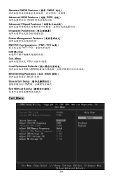
Standard CMOS Features(標準 CMOS Advanced BIOS Features(進階 BIOS Award Advanced Chipset Features Integrated Peripherals Power Management Features PNP/PCI Configurations(PNP/PCI PnP/PCI H/W Monitor Cell_Menu CPU Load Optimized Defaults BIOS BIOS Setting Password(設定 BIOS BIOS 密碼。 Save & Exit Setup CMOS Exit Without Saving Cell_Menu 59
Standard CMOS Features(標準 CMOS Advanced BIOS Features(進階 BIOS Award Advanced Chipset Features Integrated Peripherals Power Management Features PNP/PCI Configurations(PNP/PCI PnP/PCI H/W Monitor Cell_Menu CPU Load Optimized Defaults BIOS BIOS Setting Password(設定 BIOS BIOS 密碼。 Save & Exit Setup CMOS Exit Without Saving Cell_Menu 59


