
User Guide
Page 4
... guide, BIOS updates, driver updates, and other information: http://www.msi.com.tw & http://www. Technical Support If a problem arises with the same or equivalent type recommended by a service personnel: † The power cord or plug is incorrectly replaced. Lay this equipment away from overheating. Never pour any add-on the enclosure are for future reference. 3. cal shock. 11. Do not leave this User's Manual...
... guide, BIOS updates, driver updates, and other information: http://www.msi.com.tw & http://www. Technical Support If a problem arises with the same or equivalent type recommended by a service personnel: † The power cord or plug is incorrectly replaced. Lay this equipment away from overheating. Never pour any add-on the enclosure are for future reference. 3. cal shock. 11. Do not leave this User's Manual...
User Guide
Page 5
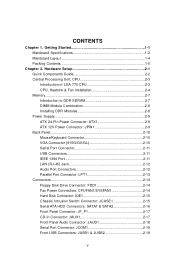
...Specifications 1-2 Mainboard Layout 1-4 Packing Contents 1-5 Chapter 2. Hardware Setup 2-1 Quick Components Guide 2-2 Central Processing Unit: CPU 2-3 Introduction of LGA 775 CPU 2-3 CPU, Heatsink & Fan Installation 2-4 Memory 2-7 Introduction to DDR SDRAM 2-7 DIMM Module Combination 2-8 Installing DDR Modules 2-8 Power Supply 2-9 ATX 24-Pin Power Connector: ATX1 2-9 ATX 12V Power Connector: JPW 1 2-9 Back Panel 2-10 Mouse/Keyboard Connector 2-10 VGA Connector (915G/GV/GL 2-10 Serial Port Connector 2-11 USB Connectors 2-11 IEEE 1394 Port 2-11 LAN (RJ-45) Jack 2-12 Audio...
...Specifications 1-2 Mainboard Layout 1-4 Packing Contents 1-5 Chapter 2. Hardware Setup 2-1 Quick Components Guide 2-2 Central Processing Unit: CPU 2-3 Introduction of LGA 775 CPU 2-3 CPU, Heatsink & Fan Installation 2-4 Memory 2-7 Introduction to DDR SDRAM 2-7 DIMM Module Combination 2-8 Installing DDR Modules 2-8 Power Supply 2-9 ATX 24-Pin Power Connector: ATX1 2-9 ATX 12V Power Connector: JPW 1 2-9 Back Panel 2-10 Mouse/Keyboard Connector 2-10 VGA Connector (915G/GV/GL 2-10 Serial Port Connector 2-11 USB Connectors 2-11 IEEE 1394 Port 2-11 LAN (RJ-45) Jack 2-12 Audio...
User Guide
Page 6
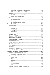
...Entering Setup 3-2 Selecting the First Boot Device 3-2 Control Keys 3-2 Getting Help 3-2 Main Menu 3-2 Default Settings 3-2 The Main Menu 3-3 Standard CMOS Features 3-6 Advanced BIOS Features 3-8 Advanced Chipset Features 3-11 Integrated Peripherals 3-12 Power Management Features 3-15 PNP/PCI Configurations 3-18 H/W Monitor 3-20 Cell Menu 3-22 BIOS Setting Password 3-24 Load Fail-Safe/Optimized Defaults 3-25 Chapter 4. Channel Audio Function 4-22 vi Itroduction to Realtek ALC880 4-1 Installing the Realtek HD Audio Driver 4-2 Installation for W indows 2000/XP 4-2 Software...
...Entering Setup 3-2 Selecting the First Boot Device 3-2 Control Keys 3-2 Getting Help 3-2 Main Menu 3-2 Default Settings 3-2 The Main Menu 3-3 Standard CMOS Features 3-6 Advanced BIOS Features 3-8 Advanced Chipset Features 3-11 Integrated Peripherals 3-12 Power Management Features 3-15 PNP/PCI Configurations 3-18 H/W Monitor 3-20 Cell Menu 3-22 BIOS Setting Password 3-24 Load Fail-Safe/Optimized Defaults 3-25 Chapter 4. Channel Audio Function 4-22 vi Itroduction to Realtek ALC880 4-1 Installing the Realtek HD Audio Driver 4-2 Installation for W indows 2000/XP 4-2 Software...
User Guide
Page 9
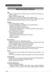
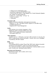
.../products/mainboard/mbd/pro_mbd_trp_list.php.) Slots † One PCI Express x16 slot (supports PCI Express Bus specification v1.0a compliant) † Three 32-bit v2.2 Master PCI bus slots (support 3.3v/5v PCI bus interface) On-Board IDE † One IDE controller on the ICH6 chipset provides IDE HDD/CD-ROM with PIO, Bus Master and Ultra DMA66/100 operation modes † Support 2 Serial ATA 150 ports On-Board Peripherals † On-Board Peripherals include: - 1 floppy port supports 1 FDD with Fan Speed Control (For the latest information about CPU...
.../products/mainboard/mbd/pro_mbd_trp_list.php.) Slots † One PCI Express x16 slot (supports PCI Express Bus specification v1.0a compliant) † Three 32-bit v2.2 Master PCI bus slots (support 3.3v/5v PCI bus interface) On-Board IDE † One IDE controller on the ICH6 chipset provides IDE HDD/CD-ROM with PIO, Bus Master and Ultra DMA66/100 operation modes † Support 2 Serial ATA 150 ports On-Board Peripherals † On-Board Peripherals include: - 1 floppy port supports 1 FDD with Fan Speed Control (For the latest information about CPU...
User Guide
Page 10
...; Controlled by onboard pinheader. Can support SPDIF Out 1394 (optional) † Supports up to 2 * 1394 ports, one 6-pin 1394 connector on rear I/O, the other is supported by VIA 6307 chipset BIOS † 4Mb FWH † The mainboard BIOS provides "Plug & Play" BIOS which detects the peripheral devices and expansion cards of the board automatically † The mainboard provides a Desktop Management Interface (DMI) function which records your mainboard specifications M ounting and Dimension † M-ATX Form...
...; Controlled by onboard pinheader. Can support SPDIF Out 1394 (optional) † Supports up to 2 * 1394 ports, one 6-pin 1394 connector on rear I/O, the other is supported by VIA 6307 chipset BIOS † 4Mb FWH † The mainboard BIOS provides "Plug & Play" BIOS which detects the peripheral devices and expansion cards of the board automatically † The mainboard provides a Desktop Management Interface (DMI) function which records your mainboard specifications M ounting and Dimension † M-ATX Form...
User Guide
Page 26
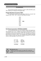
...-pin head connector. If the mainboard has a System Hardware Monitor chipset on-board, you must use a specially designed fan with +12V. Please refer to FDD, IDE HDD, case, LAN, USB Ports, IR module and CPU/System FAN. FDD1 Fan Power Connectors: CPUFAN1/SYSFAN1 The CPUFAN1(processor fan) and SYSFAN1 (system fan) support system cooling fan with speed sensor to take note that supports 360K, 720K, 1.2M, 1.44M and 2.88M floppy disk types. W hen connecting the wire to GND. GND +12V SENSOR Control...
...-pin head connector. If the mainboard has a System Hardware Monitor chipset on-board, you must use a specially designed fan with +12V. Please refer to FDD, IDE HDD, case, LAN, USB Ports, IR module and CPU/System FAN. FDD1 Fan Power Connectors: CPUFAN1/SYSFAN1 The CPUFAN1(processor fan) and SYSFAN1 (system fan) support system cooling fan with speed sensor to take note that supports 360K, 720K, 1.2M, 1.44M and 2.88M floppy disk types. W hen connecting the wire to GND. GND +12V SENSOR Control...
User Guide
Page 27
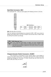
... you install two hard disks on the screen. The system will be connected to a 2-pin chassis switch. MSI Reminds You... To clear the warning, you must enter the BIOS utility and clear the record. 2 GND CINTRU 1 JCASE1 2-15 Hardware Setup Hard Disk Connector: IDE1 The mainboard has 1 IDE port and support the following function in the list. You must configure second hard drive to the hard disk documentation supplied by setting its jumper. IDE1 can connect a Master and a Slave drive. Chassis Intrusion Switch Connector: JCASE1 This connector...
... you install two hard disks on the screen. The system will be connected to a 2-pin chassis switch. MSI Reminds You... To clear the warning, you must enter the BIOS utility and clear the record. 2 GND CINTRU 1 JCASE1 2-15 Hardware Setup Hard Disk Connector: IDE1 The mainboard has 1 IDE port and support the following function in the list. You must configure second hard drive to the hard disk documentation supplied by setting its jumper. IDE1 can connect a Master and a Slave drive. Chassis Intrusion Switch Connector: JCASE1 This connector...
User Guide
Page 33
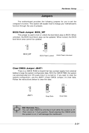
... Data 1 3 Clear Data MSI Reminds You... Follow the instructions below to change your motherboard's function through the use the JBAT1 (Clear CMOS Jumper ) to 1-2 pin position. This section will damage the mainboard. 2-21 it is turned on ; W ith the CMOS RAM, the system can be updated. 1 1 1 BIOS_WP 3 3 BIOS Flash Locked BIOS Flash Unlocked Clear CMOS Jumper: JBAT1 There is on . Hardware Setup Jumpers The motherboard provides the following jumpers for you want to clear the system configuration, use of jumpers.
... Data 1 3 Clear Data MSI Reminds You... Follow the instructions below to change your motherboard's function through the use the JBAT1 (Clear CMOS Jumper ) to 1-2 pin position. This section will damage the mainboard. 2-21 it is turned on ; W ith the CMOS RAM, the system can be updated. 1 1 1 BIOS_WP 3 3 BIOS Flash Locked BIOS Flash Unlocked Clear CMOS Jumper: JBAT1 There is on . Hardware Setup Jumpers The motherboard provides the following jumpers for you want to clear the system configuration, use of jumpers.
User Guide
Page 35
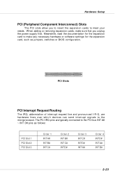
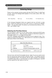
... software settings for the expansion card to make sure that you to insert the expansion cards to the PCI bus INT A# ~ INT D# pins as jumpers, switches or BIOS configuration. Meanwhile, read the documentation for the expansion card, such as follows: PCI Slot 1 PCI Slot 2 PCI Slot 3 Order 1 INT A# INT B# INT C# Order 2 INT B# INT C# INT D# Order 3 INT C# INT D# INT A# Order 4 INT D# INT A# INT B# 2-23 Hardware Setup PCI (Peripheral Component Interconnect) Slots The PCI slots...
... software settings for the expansion card to make sure that you to insert the expansion cards to the PCI bus INT A# ~ INT D# pins as jumpers, switches or BIOS configuration. Meanwhile, read the documentation for the expansion card, such as follows: PCI Slot 1 PCI Slot 2 PCI Slot 3 Order 1 INT A# INT B# INT C# Order 2 INT B# INT C# INT D# Order 3 INT C# INT D# INT A# Order 4 INT D# INT A# INT B# 2-23 Hardware Setup PCI (Peripheral Component Interconnect) Slots The PCI slots...
User Guide
Page 37
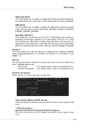
... Boot Device You are allowed to boot from the selected device. Select First Boot Device Floppy IDE-0 CDROM : 1st Floppy : IBM-DTLA-307038 : ATAPI CD-ROM DRIVE 40X M [Up/Dn] Select [RETURN] Boot [ESC] cancel The boot menu will not make changes to the settings in time. W hen the message below appears on the screen, press to enter Setup. When the same message as listed above appears on the screen, press key...
... Boot Device You are allowed to boot from the selected device. Select First Boot Device Floppy IDE-0 CDROM : 1st Floppy : IBM-DTLA-307038 : ATAPI CD-ROM DRIVE 40X M [Up/Dn] Select [RETURN] Boot [ESC] cancel The boot menu will not make changes to the settings in time. W hen the message below appears on the screen, press to enter Setup. When the same message as listed above appears on the screen, press key...
User Guide
Page 42
... floppy drives installed. Settings: [Auto], [Enabled], [Disabled]. S.M.A.R.T is a utility that is detected at boot. BIOS Setup LBA/Large Mode This item allows you to predict hard disk failure. This allows you to activate the S.M.A.R.T. (Self-Monitoring Analysis & Reporting Technology) capability for any detected error. Available options: [Disabled], [360 KB, 51/4], [1.2 MB, 51/4], [720 KB, 3 1/2], [1.44 MB, 3 1/2], [2. 88MB, 3 1/2]. Setting options: [Auto], [Disabled]. DMA Mode This item allows you to enable or disable the DMA (Direct Memory Access) mode. Available...
... floppy drives installed. Settings: [Auto], [Enabled], [Disabled]. S.M.A.R.T is a utility that is detected at boot. BIOS Setup LBA/Large Mode This item allows you to predict hard disk failure. This allows you to activate the S.M.A.R.T. (Self-Monitoring Analysis & Reporting Technology) capability for any detected error. Available options: [Disabled], [360 KB, 51/4], [1.2 MB, 51/4], [720 KB, 3 1/2], [1.44 MB, 3 1/2], [2. 88MB, 3 1/2]. Setting options: [Auto], [Disabled]. DMA Mode This item allows you to enable or disable the DMA (Direct Memory Access) mode. Available...
User Guide
Page 44
..., you to select which version to show the company logo on the bootup screen. For more information on the full screen at boot. [Disabled] Shows the POST messages at boot. 3-9 Settings: [1.4], [1.1]. Due to compliance with HT Technology; * Chipset: An Intel® Chipset that supports HT Technology; * BIOS: A BIOS that supports HT Technology and has it can enable C1E Support to select the MPS version supported by your operating system. BIOS Setup MSI Reminds You...
..., you to select which version to show the company logo on the bootup screen. For more information on the full screen at boot. [Disabled] Shows the POST messages at boot. 3-9 Settings: [1.4], [1.1]. Due to compliance with HT Technology; * Chipset: An Intel® Chipset that supports HT Technology; * BIOS: A BIOS that supports HT Technology and has it can enable C1E Support to select the MPS version supported by your operating system. BIOS Setup MSI Reminds You...
User Guide
Page 46
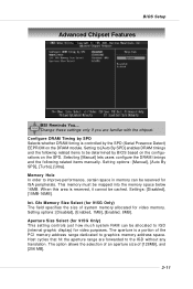
... (Serial Presence Detect) EEPROM on the SPD. W hen this area is reserved, it cannot be mapped into the memory space below 16MB. The aperture is controlled by BIOS based on the configurations on the DRAM module. BIOS Setup Advanced Chipset Features MSI Reminds You... This memory must be cached. Change these settings only if you are forwarded to IGD (internal graphic display) for video memory. Setting options: [Disabled], [Enabled, 1MB], [Enabled, 8MB]. Configure DRAM Timing...
... (Serial Presence Detect) EEPROM on the SPD. W hen this area is reserved, it cannot be mapped into the memory space below 16MB. The aperture is controlled by BIOS based on the configurations on the DRAM module. BIOS Setup Advanced Chipset Features MSI Reminds You... This memory must be cached. Change these settings only if you are forwarded to IGD (internal graphic display) for video memory. Setting options: [Disabled], [Enabled, 1MB], [Enabled, 8MB]. Configure DRAM Timing...
User Guide
Page 47
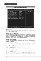
...or disable onboard IDE RAID controller. Setting options: [Enabled], [Disabled]. Onboard LAN Option ROM The item enables or disables the initialization of the onboard LAN Boot ROMs during bootup. OnBoard IEEE1394 Controller (Optional) This setting is used to use any USB 1.1/2.0 driver installed, such as DOS. Setting options: [Enabled], [Disabled]. USB Device Legacy Support Set to [Enabled] if you need to enable/disable the onboard IEEE 1394 controller. The field is optional. It appears only when your mainboard supports IDE RAID function. 3-12 Selecting [Disabled] will speed up...
...or disable onboard IDE RAID controller. Setting options: [Enabled], [Disabled]. Onboard LAN Option ROM The item enables or disables the initialization of the onboard LAN Boot ROMs during bootup. OnBoard IEEE1394 Controller (Optional) This setting is used to use any USB 1.1/2.0 driver installed, such as DOS. Setting options: [Enabled], [Disabled]. USB Device Legacy Support Set to [Enabled] if you need to enable/disable the onboard IEEE 1394 controller. The field is optional. It appears only when your mainboard supports IDE RAID function. 3-12 Selecting [Disabled] will speed up...
User Guide
Page 48
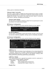
...to use other controller cards to enable the onboard Azalia controller. Selecting [Enabled] allows the mainboard to connect an audio device. BIOS Setup Setting options: [Enabled], [Disabled]. Onboard Audio Mode Set this option to [Azalia] or [AC97] to select the front panel audio function according to the case you to specify that the IDE controller on the PCI local bus has bus mastering capability. I /O port addresses of the onboard Serial Port 1 (COM A) / Serial Port 2 (COM B). COM Port 2 Mode This setting allows you purchased, IDE Devices Configuration Press to enter...
...to use other controller cards to enable the onboard Azalia controller. Selecting [Enabled] allows the mainboard to connect an audio device. BIOS Setup Setting options: [Enabled], [Disabled]. Onboard Audio Mode Set this option to [Azalia] or [AC97] to select the front panel audio function according to the case you to specify that the IDE controller on the PCI local bus has bus mastering capability. I /O port addresses of the onboard Serial Port 1 (COM A) / Serial Port 2 (COM B). COM Port 2 Mode This setting allows you purchased, IDE Devices Configuration Press to enter...
User Guide
Page 50
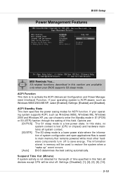
...-related functions described in memory will be used to activate the ACPI (Advanced Configuration and Power Management Interface) Function. In this section are : [S1/POS] The S1 sleep mode is to restore the system when a "wake up" event occurs. [Auto] BIOS determines the best setting automatically. ACPI Function This item is a low power state. BIOS Setup Power Management Features MSI Reminds You... If your BIOS supports S3 sleep mode. Settings: [Disabled], [1], [2], [4], [8], [10], 3-15...
...-related functions described in memory will be used to activate the ACPI (Advanced Configuration and Power Management Interface) Function. In this section are : [S1/POS] The S1 sleep mode is to restore the system when a "wake up" event occurs. [Auto] BIOS determines the best setting automatically. ACPI Function This item is a low power state. BIOS Setup Power Management Features MSI Reminds You... If your BIOS supports S3 sleep mode. Settings: [Disabled], [1], [2], [4], [8], [10], 3-15...
User Guide
Page 54
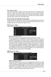
..., every PCI device can hold the bus before another takes over. PCI Slot1 IRQ, PCI Slot2 IRQ, PCI Slot3 IRQ These items specify the IRQ line for each PCI slot. IRQ Resource Setup Press and the following sub-menu appears. If more DMAs must be removed from the available DMAs passed to devices that the system DMA (Direct Memory Access) channel is used by the system BIOS. Setting options...
..., every PCI device can hold the bus before another takes over. PCI Slot1 IRQ, PCI Slot2 IRQ, PCI Slot3 IRQ These items specify the IRQ line for each PCI slot. IRQ Resource Setup Press and the following sub-menu appears. If more DMAs must be removed from the available DMAs passed to devices that the system DMA (Direct Memory Access) channel is used by the system BIOS. Setting options...
User Guide
Page 56
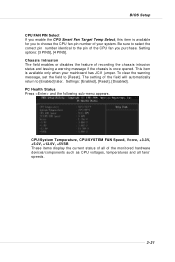
... display the current status of all fans' speeds. 3-21 Settings: [Enabled], [Reset], [Disabled]. The setting of the field will automatically return to the pin of your mainboard has JCI1 jumper. This item is once opened. To clear the warning message, set the field to choose the CPU fan pin number of the CPU fan you to [Reset]. Setting options: [3 PINS], [4 PINS]. Chassis Intrusion The field enables or disables the feature of the monitored hardware devices/components such as CPU voltages, temperatures...
... display the current status of all fans' speeds. 3-21 Settings: [Enabled], [Reset], [Disabled]. The setting of the field will automatically return to the pin of your mainboard has JCI1 jumper. This item is once opened. To clear the warning message, set the field to choose the CPU fan pin number of the CPU fan you to [Reset]. Setting options: [3 PINS], [4 PINS]. Chassis Intrusion The field enables or disables the feature of the monitored hardware devices/components such as CPU voltages, temperatures...
User Guide
Page 62
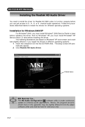
... setup screen will automatically appear. 2. Click Realtek HD Audio Driver. channel audio operations. Click here MSI Reminds You... M S-7133 M -ATX M ainboard Installing the Realtek HD Audio Driver You need to install the driver for Realtek ALC880 codec to function properly before installing the driver. The HD Audio Configuration software utility is under continuous update to install the drivers for different operating systems. Installation for reference only. 4-2 Insert the companion CD into the CD-ROM drive...
... setup screen will automatically appear. 2. Click Realtek HD Audio Driver. channel audio operations. Click here MSI Reminds You... M S-7133 M -ATX M ainboard Installing the Realtek HD Audio Driver You need to install the driver for Realtek ALC880 codec to function properly before installing the driver. The HD Audio Configuration software utility is under continuous update to install the drivers for different operating systems. Installation for reference only. 4-2 Insert the companion CD into the CD-ROM drive...
User Guide
Page 85
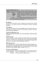
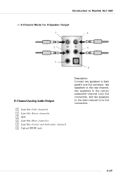
Introduction to Realtek ALC 880 n 8-Channel Mode for 8-Speaker Output 1 4 2 5 3 6 8-Channel Analog Audio Output 1 Line Out (Side channels) 2 Line Out (Front channels) 3 MIC 4 Line Out (Rear channels) 5 Line Out (Center and Subwoofer channel) 6 Optical SPDIF jack Description: Connect two speakers to back panel's Line Out connector, two speakers to the rear-channel, two speakers to the center/ subwoofer-channel Line Out connectors, and two speakers to the side-channel Line Out connectors. 4-25
Introduction to Realtek ALC 880 n 8-Channel Mode for 8-Speaker Output 1 4 2 5 3 6 8-Channel Analog Audio Output 1 Line Out (Side channels) 2 Line Out (Front channels) 3 MIC 4 Line Out (Rear channels) 5 Line Out (Center and Subwoofer channel) 6 Optical SPDIF jack Description: Connect two speakers to back panel's Line Out connector, two speakers to the rear-channel, two speakers to the center/ subwoofer-channel Line Out connectors, and two speakers to the side-channel Line Out connectors. 4-25

