User Guide
Page 5
...CPU 2-3 Example of CPU Core Speed Derivation Procedure 2-3 Memory Speed/CPU FSB Support Matrix 2-3 CPU Installation Procedures for Socket 478 2-5 Installing the CPU Fan 2-5 Memory ...2-7 Introduction to DDR SDRAM 2-7 DDR Population Rules 2-7 Dual-channel DDR Introduction 2-8 Installing DDR Modules 2-8 Power Supply ...2-9 ATX 20-Pin Power Connector: ATX1 2-9 ATX... Interference Statement ii Copyright Notice ...iii Revision History ...iii Safety Instructions ...iv Technical Support ...iv Chapter 1. Getting Started 1-1 Mainboard Specifications 1-2 Mainboard Layout 1-4 Chapter 2.
...CPU 2-3 Example of CPU Core Speed Derivation Procedure 2-3 Memory Speed/CPU FSB Support Matrix 2-3 CPU Installation Procedures for Socket 478 2-5 Installing the CPU Fan 2-5 Memory ...2-7 Introduction to DDR SDRAM 2-7 DDR Population Rules 2-7 Dual-channel DDR Introduction 2-8 Installing DDR Modules 2-8 Power Supply ...2-9 ATX 20-Pin Power Connector: ATX1 2-9 ATX... Interference Statement ii Copyright Notice ...iii Revision History ...iii Safety Instructions ...iv Technical Support ...iv Chapter 1. Getting Started 1-1 Mainboard Specifications 1-2 Mainboard Layout 1-4 Chapter 2.
User Guide
Page 8
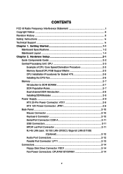
...For the latest information about CPU, please visit http://www.msi.com.tw/program/ products/mainboard/mbd/pro_mbd_cpu_support.php) Chipset h Intel® 865PE / 848P chipset - Supports 400/533/800MHz Intel NetBurst micro-architecture bus. - h Supports Dual-channel (for 865PE only) DDR 266/333/...to four Ultra ATA drives. MS-6788 ATX Mainboard Mainboard Specifications CPU h Supports Intel® P4 Northwood / Prescott (Socket 478) processors. Supports AGP 8X/4X interface. - Supports DDR266/333/400 memory interface. Up to 2GB (for 848P) / 3GB (for 865PE only). PCI Master v2.3. - h Five...
...For the latest information about CPU, please visit http://www.msi.com.tw/program/ products/mainboard/mbd/pro_mbd_cpu_support.php) Chipset h Intel® 865PE / 848P chipset - Supports 400/533/800MHz Intel NetBurst micro-architecture bus. - h Supports Dual-channel (for 865PE only) DDR 266/333/...to four Ultra ATA drives. MS-6788 ATX Mainboard Mainboard Specifications CPU h Supports Intel® P4 Northwood / Prescott (Socket 478) processors. Supports AGP 8X/4X interface. - Supports DDR266/333/400 memory interface. Up to 2GB (for 848P) / 3GB (for 865PE only). PCI Master v2.3. - h Five...
User Guide
Page 14
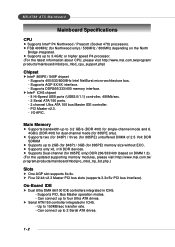
...beyond product specifications is designed to prevent overheating. Overclocking This motherboard is not recommended. We do not have the heat sink and cooling fan, contact your components are installing the CPU, make sure the CPU has a heat sink and a cooling fan attached on ... CPU, please visit http://www.msi.com.tw/ program/products/mainboard/mbd/pro_mbd_cpu_support.php Example of CPU Core Speed Derivation Procedure If CPU Clock Core/Bus ratio then CPU core speed = 200MHz = 12 = Host Clock x Core/Bus ratio = 200MHz x 12 = 2.4 GHz Memory Speed/CPU FSB Support Matrix...
...beyond product specifications is designed to prevent overheating. Overclocking This motherboard is not recommended. We do not have the heat sink and cooling fan, contact your components are installing the CPU, make sure the CPU has a heat sink and a cooling fan attached on ... CPU, please visit http://www.msi.com.tw/ program/products/mainboard/mbd/pro_mbd_cpu_support.php Example of CPU Core Speed Derivation Procedure If CPU Clock Core/Bus ratio then CPU core speed = 200MHz = 12 = Host Clock x Core/Bus ratio = 200MHz x 12 = 2.4 GHz Memory Speed/CPU FSB Support Matrix...

User Guide
Page 20
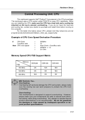
...used to provide power to an ATX power supply. Hardware Setup Power Supply The mainboard supports ATX power supply for system stability. 2-9 ATX 20-Pin Power Connector: ATX1 This connector allows you to connect to the CPU. 3 4 1 2 JPW1 JPW1 Pin Definition PIN SIGNAL 1 GND 2 GND 3 12V 4 12V MSI Reminds You... Then push down... 6 5V 16 7 GND 17 8 PW_OK 18 9 5V_SB 19 10 12V 20 SIGNAL 3.3V -12V GND PS_ON GND GND GND -5V 5V 5V ATX 12V Power Connector: JPW1 This 12V power connector is inserted in the proper orientation and the pins are installed properly to the...
...used to provide power to an ATX power supply. Hardware Setup Power Supply The mainboard supports ATX power supply for system stability. 2-9 ATX 20-Pin Power Connector: ATX1 This connector allows you to connect to the CPU. 3 4 1 2 JPW1 JPW1 Pin Definition PIN SIGNAL 1 GND 2 GND 3 12V 4 12V MSI Reminds You... Then push down... 6 5V 16 7 GND 17 8 PW_OK 18 9 5V_SB 19 10 12V 20 SIGNAL 3.3V -12V GND PS_ON GND GND GND -5V 5V 5V ATX 12V Power Connector: JPW1 This 12V power connector is inserted in the proper orientation and the pins are installed properly to the...
User Guide
Page 25
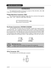
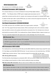
GND +12V Sensor CPUFAN1 GND +12V Sensor SYSFAN1 MSI Reminds You... 1. Floppy Disk Drive Connector: FDD1 The mainboard provides a ...CD-ROM audio connector. CD1 R GND L 2-14 Please refer to FDD, IDE HDD, LAN, USB Ports, and CPU/System/Power Supply FAN. CD-In Connector: CD1 The connector is Ground and should be connected to the +12V, ...the black wire is for proper CPU cooling fan. 2. It supports three-pin head connector. MS-6788 ATX Mainboard Connectors The mainboard provides connectors to connect to the recommend CPU fans at Intel® official website. FDD1 Fan...
GND +12V Sensor CPUFAN1 GND +12V Sensor SYSFAN1 MSI Reminds You... 1. Floppy Disk Drive Connector: FDD1 The mainboard provides a ...CD-ROM audio connector. CD1 R GND L 2-14 Please refer to FDD, IDE HDD, LAN, USB Ports, and CPU/System/Power Supply FAN. CD-In Connector: CD1 The connector is Ground and should be connected to the +12V, ...the black wire is for proper CPU cooling fan. 2. It supports three-pin head connector. MS-6788 ATX Mainboard Connectors The mainboard provides connectors to connect to the recommend CPU fans at Intel® official website. FDD1 Fan...
User Guide
Page 42
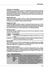
... protection that monitors your disk status to run Setup. For more information on and the head will move data from a hard disk that supports HT Technology. BIOS Setup S.M.A.R.T. First A: will increase the system performance. Floppy Drive Seek This setting causes the BIOS to a safe place...during the boot process: the drive activity light will come on Hyper-threading Technology, go to enable or disable the Intel Hyper Threading CPU function. MSI Reminds You... S.M.A.R.T is a utility that is going to fail to search for Hard Disks This allows you cannot run the OS/2&#...
... protection that monitors your disk status to run Setup. For more information on and the head will move data from a hard disk that supports HT Technology. BIOS Setup S.M.A.R.T. First A: will increase the system performance. Floppy Drive Seek This setting causes the BIOS to a safe place...during the boot process: the drive activity light will come on Hyper-threading Technology, go to enable or disable the Intel Hyper Threading CPU function. MSI Reminds You... S.M.A.R.T is a utility that is going to fail to search for Hard Disks This allows you cannot run the OS/2&#...
User Guide
Page 43
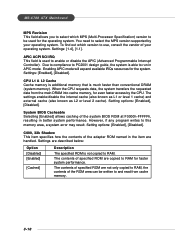
... [1.1]. Due to compliance to PC2001 design guide, the system is used for faster system performance. CPU L1 & L2 Cache Cache memory is additional memory that is not copied to RAM. When the CPU requests data, the system transfers the requested data from cache memory. 3-10 Setting options: [Enabled... Enabling APIC mode will expand available IRQs resources for even faster access by your operating system. Settings: [Enabled], [Disabled]. MS-6788 ATX Mainboard MPS Revision This field allows you to select which version to use, consult the vendor of your operating system. You need to...
... [1.1]. Due to compliance to PC2001 design guide, the system is used for faster system performance. CPU L1 & L2 Cache Cache memory is additional memory that is not copied to RAM. When the CPU requests data, the system transfers the requested data from cache memory. 3-10 Setting options: [Enabled... Enabling APIC mode will expand available IRQs resources for even faster access by your operating system. Settings: [Enabled], [Disabled]. MS-6788 ATX Mainboard MPS Revision This field allows you to select which version to use, consult the vendor of your operating system. You need to...
User Guide
Page 46
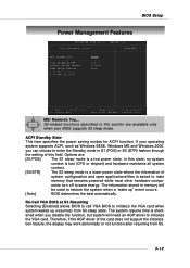
...S3. 3-13 Therefore, if the AGP driver of system configuration and open applications/files is a low power state. BIOS Setup Power Management Features MSI Reminds You... S3-related functions described in S1 (POS) or S3 (STR) fashion through the setting of this state, no system context is lost... (CPU or chipset) and hardware maintains all system context. [S3/STR] The S3 sleep mode is a lower power state where the information of the card does not support the initialization feature, the display may work abnormally or not function...
...S3. 3-13 Therefore, if the AGP driver of system configuration and open applications/files is a low power state. BIOS Setup Power Management Features MSI Reminds You... S3-related functions described in S1 (POS) or S3 (STR) fashion through the setting of this state, no system context is lost... (CPU or chipset) and hardware maintains all system context. [S3/STR] The S3 sleep mode is a lower power state where the information of the card does not support the initialization feature, the display may work abnormally or not function...
User Guide
Page 7
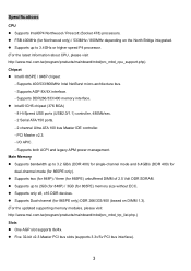
.../400 (based on the North Bridge integrated. Specifications CPU z Supports Intel®P4 Northwood / Prescott (Socket 478) processors. z FSB 400MHz (for 865PE) unbuffered DIMM of 2.5 Volt DDR SDRAM. z Supports up to 3.4GHz or higher speed P4 processor. (For the latest information about CPU, please visit http://www.msi.com.tw/program/products/mainboard/mbd/pro_mbd_cpu_support.php...
.../400 (based on the North Bridge integrated. Specifications CPU z Supports Intel®P4 Northwood / Prescott (Socket 478) processors. z FSB 400MHz (for 865PE) unbuffered DIMM of 2.5 Volt DDR SDRAM. z Supports up to 3.4GHz or higher speed P4 processor. (For the latest information about CPU, please visit http://www.msi.com.tw/program/products/mainboard/mbd/pro_mbd_cpu_support.php...
User Guide
Page 9
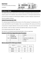
... CPU, please visit http://www.msi.com.tw/program/products/mainboard/mbd/pro_mbd_cpu_support.php) Example of CPU Core Speed Derivation Procedure If CPU Clock Core/Bus ratio then CPU core speed = 200MHz = 12 = Host Clock x Core/Bus ratio = 200MHz x 12 = 2.4 GHz Memory Speed/CPU FSB Support... and follow the installation procedures. It also provides the instructions on the mainboard. The mainboard uses a CPU socket called PGA478 for easy CPU installation. Central Processing Unit: CPU The mainboard supports Intel®Pentium®4 processors in the 478 pin package.
... CPU, please visit http://www.msi.com.tw/program/products/mainboard/mbd/pro_mbd_cpu_support.php) Example of CPU Core Speed Derivation Procedure If CPU Clock Core/Bus ratio then CPU core speed = 200MHz = 12 = Host Clock x Core/Bus ratio = 200MHz x 12 = 2.4 GHz Memory Speed/CPU FSB Support... and follow the installation procedures. It also provides the instructions on the mainboard. The mainboard uses a CPU socket called PGA478 for easy CPU installation. Central Processing Unit: CPU The mainboard supports Intel®Pentium®4 processors in the 478 pin package.
User Guide
Page 11
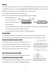
... supply, make sure all components installed properly and ensure no damage to the CPU. To 5V GND GND GND 3. 3V 5V - 5V GN D PS_ ON -12 V connect to an ATX power supply. Vo l t Notc h 2. The DDR DIMM has only one DIMM module must be caused. Floppy Disk Drive ... inserted in until the golden finger on the memory module is used to provide power to be installed. (For the updated supporting memory modules, please visit http://www.msi.com.tw/program/products/mainboard/mbd/pro_mbd_trp_list.php.) 1. Insert the DIMM memory module vertically into the connector. 12 5V V ...
... supply, make sure all components installed properly and ensure no damage to the CPU. To 5V GND GND GND 3. 3V 5V - 5V GN D PS_ ON -12 V connect to an ATX power supply. Vo l t Notc h 2. The DDR DIMM has only one DIMM module must be caused. Floppy Disk Drive ... inserted in until the golden finger on the memory module is used to provide power to be installed. (For the updated supporting memory modules, please visit http://www.msi.com.tw/program/products/mainboard/mbd/pro_mbd_trp_list.php.) 1. Insert the DIMM memory module vertically into the connector. 12 5V V ...
User Guide
Page 12
...Secondary IDE Connector): IDE2 can connect a Master and a Slave drive. When connecting the wire to the connectors, always take advantage of the CPU fan control. You can install the PC Alert utility that provides PIO mode 0~5, Bus Master, and Ultra DMA 33/66/100 function. These ...two hard disks on -board, you need to take note that the red wire is the positive and should be connected to IDE1. CPUFAN1 supports the fan control. MSI Reminds You... R L S-Bracket Connector: JSP1 (Optional) The connector allows you must use a specially designed fan with +12V. The S-...
...Secondary IDE Connector): IDE2 can connect a Master and a Slave drive. When connecting the wire to the connectors, always take advantage of the CPU fan control. You can install the PC Alert utility that provides PIO mode 0~5, Bus Master, and Ultra DMA 33/66/100 function. These ...two hard disks on -board, you need to take note that the red wire is the positive and should be connected to IDE1. CPUFAN1 supports the fan control. MSI Reminds You... R L S-Bracket Connector: JSP1 (Optional) The connector allows you must use a specially designed fan with +12V. The S-...


