User Guide
Page 3
... Corporation. Revision History Revision V1.0 V1.1 V2.0 Revision History First release for PCB 1.X with Intel® 848P & Intel® ICH5 Audio driver updates First release for PCB 2.X with Intel® 865PE/848P & Intel® ICH5 Date August 2003 October 2003 February 2004 iii PCMCIA and CardBus are registered trademarks or trademarks of...
... Corporation. Revision History Revision V1.0 V1.1 V2.0 Revision History First release for PCB 1.X with Intel® 848P & Intel® ICH5 Audio driver updates First release for PCB 2.X with Intel® 865PE/848P & Intel® ICH5 Date August 2003 October 2003 February 2004 iii PCMCIA and CardBus are registered trademarks or trademarks of...
User Guide
Page 5
... Memory ...2-7 Introduction to DDR SDRAM 2-7 DDR Population Rules 2-7 Dual-channel DDR Introduction 2-8 Installing DDR Modules 2-8 Power Supply ...2-9 ATX 20-Pin Power Connector: ATX1 2-9 ATX 12V Power Connector: JPW1 2-9 Back Panel ...2-10 Mouse Connector 2-10 Keyboard Connector 2-10 Serial Port Connector: COM A 2-11 USB... Connectors 2-11 SPDIF-out Port Connector 2-11 RJ-45 LAN Jack: 10/100 LAN (8100C) /Giga-bit LAN (8110S) (Optional 2-12 Audio ...
... Memory ...2-7 Introduction to DDR SDRAM 2-7 DDR Population Rules 2-7 Dual-channel DDR Introduction 2-8 Installing DDR Modules 2-8 Power Supply ...2-9 ATX 20-Pin Power Connector: ATX1 2-9 ATX 12V Power Connector: JPW1 2-9 Back Panel ...2-10 Mouse Connector 2-10 Keyboard Connector 2-10 Serial Port Connector: COM A 2-11 USB... Connectors 2-11 SPDIF-out Port Connector 2-11 RJ-45 LAN Jack: 10/100 LAN (8100C) /Giga-bit LAN (8110S) (Optional 2-12 Audio ...

User Guide
Page 6
... Connectors: JUSB2 & JUSB3 2-15 Serial ATA HDD Connectors: SATA1, SATA2 2-16 S-Bracket (SPDIF) Connector: JSP1 (Optional 2-17 Front Panel Connectors: JFP1 & JFP2 2-18 Front Panel Audio Connector: JAUD1 2-19 D-Bracket™ 2 Connector: JDB1 (Optional 2-20 Jumpers ...2-21 Clear CMOS Jumper: JBAT1 2-21 Slots ...2-22 AGP (Accelerated Graphics Port) Slot 2-22 PCI...
... Connectors: JUSB2 & JUSB3 2-15 Serial ATA HDD Connectors: SATA1, SATA2 2-16 S-Bracket (SPDIF) Connector: JSP1 (Optional 2-17 Front Panel Connectors: JFP1 & JFP2 2-18 Front Panel Audio Connector: JAUD1 2-19 D-Bracket™ 2 Connector: JDB1 (Optional 2-20 Jumpers ...2-21 Clear CMOS Jumper: JBAT1 2-21 Slots ...2-22 AGP (Accelerated Graphics Port) Slot 2-22 PCI...
User Guide
Page 9
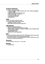
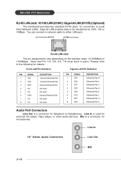
...The mainboard BIOS provides "Plug & Play" BIOS which records your mainboard specifications. Dimension h ATX Form Factor: 29.5 cm (L) x 21.0 cm (W). h 6 channels software audio codec ALC655. - Compliance with PCI v2.2. - Meet PC2001 audio performance requirement. Compliant with AC97 v2.2 Spec. - Mounting h 6 mounting holes. 1-3...Rear * 4/ Front * 4) - 1 Line-In/Line-Out/Mic-In port - 1 RJ45 LAN jack (Optional) - 1 RCA SPDIF Out Audio h AC'97 link controller integrated in one chip. - Supports 10Mb/s, 100Mb/s and 1000Mb/s (1000Mb/s is only for Realtek 8110S) auto-negotiation operation. -
...The mainboard BIOS provides "Plug & Play" BIOS which records your mainboard specifications. Dimension h ATX Form Factor: 29.5 cm (L) x 21.0 cm (W). h 6 channels software audio codec ALC655. - Compliance with PCI v2.2. - Meet PC2001 audio performance requirement. Compliant with AC97 v2.2 Spec. - Mounting h 6 mounting holes. 1-3...Rear * 4/ Front * 4) - 1 Line-In/Line-Out/Mic-In port - 1 RJ45 LAN jack (Optional) - 1 RCA SPDIF Out Audio h AC'97 link controller integrated in one chip. - Supports 10Mb/s, 100Mb/s and 1000Mb/s (1000Mb/s is only for Realtek 8110S) auto-negotiation operation. -

User Guide
Page 22
... Ready Request To Send Clear To Send Ring Indicate USB Connectors The mainboard provides a UHCI (Universal Host Controller Interface) Universal Serial Bus root for digital audio transmission. The ports are 16550A high speed communication ports that send/receive 16 bytes FIFOs. SPDIF-out port 2-11
... Ready Request To Send Clear To Send Ring Indicate USB Connectors The mainboard provides a UHCI (Universal Host Controller Interface) Universal Serial Bus root for digital audio transmission. The ports are 16550A high speed communication ports that send/receive 16 bytes FIFOs. SPDIF-out port 2-11
User Guide
Page 23
...pairs. You can connect a network cable to be transferred at 1000, 100 or 10Mbps. Line In 1/8" Stereo Audio Connectors Line Out MIC 2-12 Giga-bit LAN enables data to either LAN jack. MS-6788 ATX Mainboard RJ-45 LAN Jack: 10/100 LAN (8100C) /Giga-bit LAN (8110S) (Optional) The mainboard ...provides two standard RJ-45 jacks for external CD player, Tape player, or other audio devices. Line In is a connector for Speakers or Headphones...
...pairs. You can connect a network cable to be transferred at 1000, 100 or 10Mbps. Line In 1/8" Stereo Audio Connectors Line Out MIC 2-12 Giga-bit LAN enables data to either LAN jack. MS-6788 ATX Mainboard RJ-45 LAN Jack: 10/100 LAN (8100C) /Giga-bit LAN (8110S) (Optional) The mainboard ...provides two standard RJ-45 jacks for external CD player, Tape player, or other audio devices. Line In is a connector for Speakers or Headphones...
User Guide
Page 25
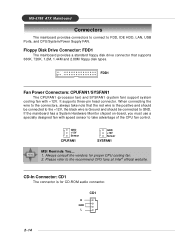
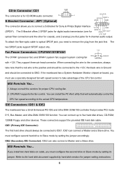
... a standard floppy disk drive connector that the red wire is the positive and should be connected to GND. Always consult the vendors for CD-ROM audio connector. Please refer to FDD, IDE HDD, LAN, USB Ports, and CPU/System/Power Supply FAN. CD-In Connector: CD1 The connector is... note that supports 360K, 720K, 1.2M, 1.44M and 2.88M floppy disk types. CD1 R GND L 2-14 GND +12V Sensor CPUFAN1 GND +12V Sensor SYSFAN1 MSI Reminds You... 1. MS-6788 ATX Mainboard Connectors The mainboard provides connectors to connect to the recommend CPU fans at Intel® official website.
... a standard floppy disk drive connector that the red wire is the positive and should be connected to GND. Always consult the vendors for CD-ROM audio connector. Please refer to FDD, IDE HDD, LAN, USB Ports, and CPU/System/Power Supply FAN. CD-In Connector: CD1 The connector is... note that supports 360K, 720K, 1.2M, 1.44M and 2.88M floppy disk types. CD1 R GND L 2-14 GND +12V Sensor CPUFAN1 GND +12V Sensor SYSFAN1 MSI Reminds You... 1. MS-6788 ATX Mainboard Connectors The mainboard provides connectors to connect to the recommend CPU fans at Intel® official website.

User Guide
Page 28
...output 4 (No Pin) 5 GND Ground 6 SPDFI 7 LFE-OUT Audio bass output 8 SOUT-R 9 CET-OUT Audio center output 10 SOUT-L 11 GND Ground 12 GND DESCRIPTION VDD 3.3V Key S/PDIF input Audio right surrounding output Audio left surrounding output Ground Optional S-Bracket Connect to remove the plug from ...first. To attach the fiber-optic cable to optical SPDIF jack, you to connect a S-Bracket for 4-channel audio output. The S-Bracket offers 2 SPDIF jacks for digital audio transmission (one for optical fiber connection and the other for coaxial), and 2 analog Line-Out jacks for ...
...output 4 (No Pin) 5 GND Ground 6 SPDFI 7 LFE-OUT Audio bass output 8 SOUT-R 9 CET-OUT Audio center output 10 SOUT-L 11 GND Ground 12 GND DESCRIPTION VDD 3.3V Key S/PDIF input Audio right surrounding output Audio left surrounding output Ground Optional S-Bracket Connect to remove the plug from ...first. To attach the fiber-optic cable to optical SPDIF jack, you to connect a S-Bracket for 4-channel audio output. The S-Bracket offers 2 SPDIF jacks for digital audio transmission (one for optical fiber connection and the other for coaxial), and 2 analog Line-Out jacks for ...

User Guide
Page 30
...for future use to control headphone amplifier 8 KEY No pin 9 AUD_FPOUT_L Left channel audio signal to the rear audio ports. If you to connect to the front panel audio and is compliant with Intel® Front Panel I/O Connectivity Design Guide. 2 10... 1 AUD_MIC Front panel microphone input signal 2 AUD_GND Ground used by analog audio circuits 3 AUD_MIC_BIAS Microphone power 4 AUD_VCC Filtered +5V used by analog audio circuits 5 AUD_FPOUT_R Right channel audio signal to front panel 6 AUD_RET_R Right channel audio signal return from front panel MSI Reminds You...
...for future use to control headphone amplifier 8 KEY No pin 9 AUD_FPOUT_L Left channel audio signal to the rear audio ports. If you to connect to the front panel audio and is compliant with Intel® Front Panel I/O Connectivity Design Guide. 2 10... 1 AUD_MIC Front panel microphone input signal 2 AUD_GND Ground used by analog audio circuits 3 AUD_MIC_BIAS Microphone power 4 AUD_VCC Filtered +5V used by analog audio circuits 5 AUD_FPOUT_R Right channel audio signal to front panel 6 AUD_RET_R Right channel audio signal return from front panel MSI Reminds You...
User Guide
Page 54
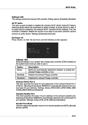
... the onboard AC'97 controller will automatically determine whether to enable or disable the onboard AC'97 (Audio Codec'97) feature. Settings: [Disabled] and [Auto]. Setting options: [Disabled], [Enabled]. AC'97 Audio This item is disabled. Onboard Serial Port A This item specifies the base I /O port address ... Port This field specifies the base I /O port addresses of the onboard parallel port. Selecting [Auto] allows AMIBIOS to connect an audio device. Parallel Port Mode This item selects the operation mode for the onboard parallel port: [ECP], [Normal], [Bi-Dir] or [EPP]. 3-21
... the onboard AC'97 controller will automatically determine whether to enable or disable the onboard AC'97 (Audio Codec'97) feature. Settings: [Disabled] and [Auto]. Setting options: [Disabled], [Enabled]. AC'97 Audio This item is disabled. Onboard Serial Port A This item specifies the base I /O port address ... Port This field specifies the base I /O port addresses of the onboard parallel port. Selecting [Auto] allows AMIBIOS to connect an audio device. Parallel Port Mode This item selects the operation mode for the onboard parallel port: [ECP], [Normal], [Bi-Dir] or [EPP]. 3-21
User Guide
Page 8
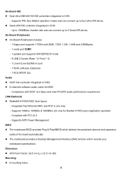
...174; 8110S/8100C Dual layout. - On-Board IDE z Dual Ultra DMA 66/100 IDE controllers integrated in ICH5. Audio z AC97 link controller integrated in ICH5. - Compliant with AC97 v2.2 Spec and meet PC2001 audio performance requirement. Supports PIO, Bus Master operation modes and can connect up to 2 Serial ATA drives. z The ...transfer rate and can connect up to four Ultra ATA drives. Integrated Fast Ethernet MAC and PHY in ICH5. - Supports ACPI Power Management. z 6 channels software audio codec ALC655. - Dimension z ATX Form Factor: 29.5 cm (L) x 21.0 cm (W).
...174; 8110S/8100C Dual layout. - On-Board IDE z Dual Ultra DMA 66/100 IDE controllers integrated in ICH5. Audio z AC97 link controller integrated in ICH5. - Compliant with AC97 v2.2 Spec and meet PC2001 audio performance requirement. Supports PIO, Bus Master operation modes and can connect up to 2 Serial ATA drives. z The ...transfer rate and can connect up to four Ultra ATA drives. Integrated Fast Ethernet MAC and PHY in ICH5. - Supports ACPI Power Management. z 6 channels software audio codec ALC655. - Dimension z ATX Form Factor: 29.5 cm (L) x 21.0 cm (W).
User Guide
Page 12
... fan. 2. Refer to the hard disk document supplied by hard disk vendors for CD-ROM audio connector. The S-Bracket offers 2 SPDIF jacks for digital audio transmission (one for 4-channel audio output. When connecting the wire to the connectors, always take advantage of the CPU fan control...the black wire is for jumper setting instructions. 8 You must configure the second drive to Slave mode by setting the jumper accordingly. MSI Reminds You... 1. MSI Reminds You... The two SPDIF jacks support SPDIF output only. +12V Fan Power Connectors: CPUFAN1/SYSFAN1 GND The CFAN1 (processor fan...
... fan. 2. Refer to the hard disk document supplied by hard disk vendors for CD-ROM audio connector. The S-Bracket offers 2 SPDIF jacks for digital audio transmission (one for 4-channel audio output. When connecting the wire to the connectors, always take advantage of the CPU fan control...the black wire is for jumper setting instructions. 8 You must configure the second drive to Slave mode by setting the jumper accordingly. MSI Reminds You... 1. MSI Reminds You... The two SPDIF jacks support SPDIF output only. +12V Fan Power Connectors: CPUFAN1/SYSFAN1 GND The CFAN1 (processor fan...

User Guide
Page 13
...specifications. JFP1 Power Power LED Switch 2 10 1 9 HD D R eset LED Switch JFP 2 Speaker 2 8 1 7 Power LED Front Panel Audio Connector: JAUD1 The front panel audio connector allows you want to clear the system configuration, use the 3 3 Kee pD at a Clear D ata JBAT1 (Clear CMOS Jumper ) to clear... data. USB 2.0 technology increases data transfer rate up to the front panel audio and is compliant with Intel®Front Panel I/O Connectivity Design Guide. MSI Reminds You... 6 10 Not to connect to the front audio header, pins 5 & 6, 9 & 10 should jumper in order to ...
...specifications. JFP1 Power Power LED Switch 2 10 1 9 HD D R eset LED Switch JFP 2 Speaker 2 8 1 7 Power LED Front Panel Audio Connector: JAUD1 The front panel audio connector allows you want to clear the system configuration, use the 3 3 Kee pD at a Clear D ata JBAT1 (Clear CMOS Jumper ) to clear... data. USB 2.0 technology increases data transfer rate up to the front panel audio and is compliant with Intel®Front Panel I/O Connectivity Design Guide. MSI Reminds You... 6 10 Not to connect to the front audio header, pins 5 & 6, 9 & 10 should jumper in order to ...
