User Guide
Page 3
...their respective owners. Trademarks All trademarks are under continual improvement and we reserve the right to the correctness of the Personal Computer Memory Card International Association. NVIDIA, the NVIDIA logo, DualNet, and nForce are registered trademarks of its contents. PCMCIA and CardBus ...® is a registered trademark of Intel Corporation. Revision History Revision V1.0 V1.1 Revision History First release with chipsets Intel® 865PE/G & Intel® ICH5 Update the Core Center photo, Modify CPU description Date March 2003 April 2003 iii AMI® is a...
...their respective owners. Trademarks All trademarks are under continual improvement and we reserve the right to the correctness of the Personal Computer Memory Card International Association. NVIDIA, the NVIDIA logo, DualNet, and nForce are registered trademarks of its contents. PCMCIA and CardBus ...® is a registered trademark of Intel Corporation. Revision History Revision V1.0 V1.1 Revision History First release with chipsets Intel® 865PE/G & Intel® ICH5 Update the Core Center photo, Modify CPU description Date March 2003 April 2003 iii AMI® is a...
User Guide
Page 5
... Core Speed Derivation Procedure 2-3 CPU Installation Procedures for Socket 478 2-5 Installing the CPU Fan 2-5 Memory 2-7 Introduction to DDR SDRAM 2-7 DDR Population Rules 2-7 Installing DDR Modules 2-8 Power Supply 2-9 ATX 20-Pin Power Connector: ATX1 2-9 v Getting Started 1-1 Mainboard Specifications 1-2 Mainboard Layout 1-4 MSI Special Features 1-5 Super Pack 1-5 Core Center 1-6 Live BIOS™/Live Driver 1-8 Live Monitor...
... Core Speed Derivation Procedure 2-3 CPU Installation Procedures for Socket 478 2-5 Installing the CPU Fan 2-5 Memory 2-7 Introduction to DDR SDRAM 2-7 DDR Population Rules 2-7 Installing DDR Modules 2-8 Power Supply 2-9 ATX 20-Pin Power Connector: ATX1 2-9 v Getting Started 1-1 Mainboard Specifications 1-2 Mainboard Layout 1-4 MSI Special Features 1-5 Super Pack 1-5 Core Center 1-6 Live BIOS™/Live Driver 1-8 Live Monitor...
User Guide
Page 9
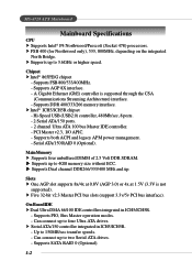
... integrated North Bridge. Supports both ACPI and legacy APM power management. - Can connect up to 150MB/sec transfer speeds. - MS-6728 ATX Mainboard Mainboard Specifications CPU h Supports Intel® P4 Northwood/Prescott (Socket 478) processors. h Intel® ICH5/ICH5R chipset - h Supports... up to 3.6GHz or higher speed. Chipset h Intel® 865PE/G chipset - Serial ATA/150 RAID 0 (Optional). Main Memory h Supports four unbuffered DIMM of 2.5 Volt DDR SDRAM. h Supports up to 4GB memory size without ECC. Slots h One AGP slot supports 8x/4x at 0.8V (...
... integrated North Bridge. Supports both ACPI and legacy APM power management. - Can connect up to 150MB/sec transfer speeds. - MS-6728 ATX Mainboard Mainboard Specifications CPU h Supports Intel® P4 Northwood/Prescott (Socket 478) processors. h Intel® ICH5/ICH5R chipset - h Supports... up to 3.6GHz or higher speed. Chipset h Intel® 865PE/G chipset - Serial ATA/150 RAID 0 (Optional). Main Memory h Supports four unbuffered DIMM of 2.5 Volt DDR SDRAM. h Supports up to 4GB memory size without ECC. Slots h One AGP slot supports 8x/4x at 0.8V (...
User Guide
Page 14
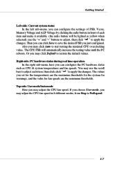
... & system temperatures and fan speeds. Getting Started Left-side: Current system status In the left sub-menu, you can configure the settings of FSB, Vcore, Memory Voltage and AGP Voltage by clicking the radio button in 8 different modes, from Stop to apply the changes. Then you just configured. Or you may...
... & system temperatures and fan speeds. Getting Started Left-side: Current system status In the left sub-menu, you can configure the settings of FSB, Vcore, Memory Voltage and AGP Voltage by clicking the radio button in 8 different modes, from Stop to apply the changes. Then you just configured. Or you may...
User Guide
Page 17
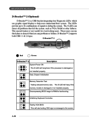
..., RAM or other failures. D-Bracket™ 2 1 2 3 4 Red Green D-Bracket™ 2 Description System Power ON 1 2 - Testing onboard memory size. The D-LED will hang here if the processor is damaged or 3 4 not installed properly. Decompressing BIOS image to the screen. 1-10 The 4...LEDs can use graphic signal display to help users understand their system. Early Chipset Initialization Memory Detection Test - This will start writing VGA sign-on message to RAM for overclocking users. MS-6728 ATX Mainboard D-Bracket™ 2 (Optional) D-Bracket™ 2 is a USB bracket ...
..., RAM or other failures. D-Bracket™ 2 1 2 3 4 Red Green D-Bracket™ 2 Description System Power ON 1 2 - Testing onboard memory size. The D-LED will hang here if the processor is damaged or 3 4 not installed properly. Decompressing BIOS image to the screen. 1-10 The 4...LEDs can use graphic signal display to help users understand their system. Early Chipset Initialization Memory Detection Test - This will start writing VGA sign-on message to RAM for overclocking users. MS-6728 ATX Mainboard D-Bracket™ 2 (Optional) D-Bracket™ 2 is a USB bracket ...
User Guide
Page 18
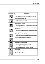
Assign Resources to 640K and extended memory above 1MB using various patterns. This will initialize IDE drive and controller. Testing base memory from 240K to all ISA. Initializing Floppy Drive Controller - Boot Attempt - This will start detecting CPU ...clock, checking type of video onboard. Then, detect and initialize the video adapter. Testing Base and Extended Memory - Operating System Booting 1-11 This will initializing Floppy Drive and controller. Getting Started D-Bracket™ 2 Description Processor Initialization - This will...
Assign Resources to 640K and extended memory above 1MB using various patterns. This will initialize IDE drive and controller. Testing base memory from 240K to all ISA. Initializing Floppy Drive Controller - Boot Attempt - This will start detecting CPU ...clock, checking type of video onboard. Then, detect and initialize the video adapter. Testing Base and Extended Memory - Operating System Booting 1-11 This will initializing Floppy Drive and controller. Getting Started D-Bracket™ 2 Description Processor Initialization - This will...
User Guide
Page 21
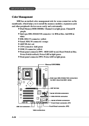
... 2.0 connector 1394 connectors Serial ATA150 connectors IDE ATA133 connector Serial ATA150 connectors Front Panel connector JFP1 Front Panel connector JFP2 1-14 h Dual Memory DDR DIMMs: Channel A in light green, Channel B purple h Intel spec IDE ATA66/100 connector: 1st IDE in blue, 2nd IDE...h Front panel connector JFP2: Power LED in light green. MS-6728 ATX Mainboard Color Management MSI has an unified color management rule for some connectors on the mainboards, which helps you to install the memory modules, expansion cards and other peripherals devices more easily and conveniently.
... 2.0 connector 1394 connectors Serial ATA150 connectors IDE ATA133 connector Serial ATA150 connectors Front Panel connector JFP1 Front Panel connector JFP2 1-14 h Dual Memory DDR DIMMs: Channel A in light green, Channel B purple h Intel spec IDE ATA66/100 connector: 1st IDE in blue, 2nd IDE...h Front panel connector JFP2: Power LED in light green. MS-6728 ATX Mainboard Color Management MSI has an unified color management rule for some connectors on the mainboards, which helps you to install the memory modules, expansion cards and other peripherals devices more easily and conveniently.
User Guide
Page 22
Hardware Setup Chapter 2. Also, it provides the instructions on connecting the peripheral devices, such as how to install the CPU, memory modules, and expansion cards, as well as the mouse, keyboard, etc. While doing the installation, be careful in holding the components and follow the installation procedures. 2-1 Hardware Setup Hardware Setup This chapter tells you how to setup the jumpers on the mainboard.
Hardware Setup Chapter 2. Also, it provides the instructions on connecting the peripheral devices, such as how to install the CPU, memory modules, and expansion cards, as well as the mouse, keyboard, etc. While doing the installation, be careful in holding the components and follow the installation procedures. 2-1 Hardware Setup Hardware Setup This chapter tells you how to setup the jumpers on the mainboard.
User Guide
Page 28
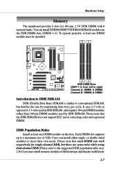
... not support ECC (error correcting code) and registered DIMM. or double-sided modules to a maximum size of different type and density on p. 2-8).Users may install memory modules of 1GB. To operate properly, at least one DIMM module must be installed. Please note that each DIMM can install either single- DDR Population... Rules Install at least one DIMM module on the DDR DIMM slots (DIMM 1~4). Hardware Setup Memory The mainboard provides 4 slots for single-channel DDR, but doubles the rate by SDR SDRAM.
... not support ECC (error correcting code) and registered DIMM. or double-sided modules to a maximum size of different type and density on p. 2-8).Users may install memory modules of 1GB. To operate properly, at least one DIMM module must be installed. Please note that each DIMM can install either single- DDR Population... Rules Install at least one DIMM module on the DDR DIMM slots (DIMM 1~4). Hardware Setup Memory The mainboard provides 4 slots for single-channel DDR, but doubles the rate by SDR SDRAM.
User Guide
Page 29
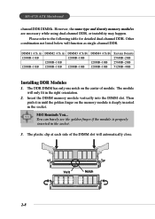
The module will only fit in the socket. 3. MSI Reminds You... You can barely see the golden finger if the module is deeply...2GB 512MB~4GB Installing DDR Modules 1. The DDR DIMM has only one notch on the memory module is properly inserted in the right orientation. 2. The plastic clip at each side of module. Insert the DIMM... memory module vertically into the DIMM slot. Then push it in the socket. MS-6728 ATX Mainboard channelDDR DIMMs. However, the same type and density memory modules are necessary while using dual-channel DDR, or...
The module will only fit in the socket. 3. MSI Reminds You... You can barely see the golden finger if the module is deeply...2GB 512MB~4GB Installing DDR Modules 1. The DDR DIMM has only one notch on the memory module is properly inserted in the right orientation. 2. The plastic clip at each side of module. Insert the DIMM... memory module vertically into the DIMM slot. Then push it in the socket. MS-6728 ATX Mainboard channelDDR DIMMs. However, the same type and density memory modules are necessary while using dual-channel DDR, or...
User Guide
Page 54
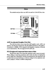
AGP is an interface specification designed for the expansion card to directly access main memory. It introduces a 66MHz, 32-bit channel for the expansion card, such as jumpers, switches or BIOS configuration. 2-33 PCI (Peripheral Component Interconnect) Slots The PCI ... 3D graphics. B AT T AGP Slot + PCI Slots AGP (Accelerated Graphics Port) Slot The AGP slot allows you to meet your needs. Hardware Setup Slots The motherboard provides one AGP slot and five 32-bit PCI bus slots. The slot supports 8x/4x AGP card.
AGP is an interface specification designed for the expansion card to directly access main memory. It introduces a 66MHz, 32-bit channel for the expansion card, such as jumpers, switches or BIOS configuration. 2-33 PCI (Peripheral Component Interconnect) Slots The PCI ... 3D graphics. B AT T AGP Slot + PCI Slots AGP (Accelerated Graphics Port) Slot The AGP slot allows you to meet your needs. Hardware Setup Slots The motherboard provides one AGP slot and five 32-bit PCI bus slots. The slot supports 8x/4x AGP card.
User Guide
Page 67
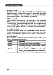
MS-6728 ATX Mainboard APIC ACPI SCI IRQ This field is not copied to RAM. However...in the item are copied to and read from the main DRAM into cache memory, for faster system performance. CPU L1 & L2 Cache Cache memory is additional memory that is able to PC2001 design guide, the system is much faster than ...conventional DRAM (system memory). When the CPU requests data, the system transfers the requested data from cache memory. 3-12 Settings: Enabled and Disabled. The setting controls the internal cache (also...
MS-6728 ATX Mainboard APIC ACPI SCI IRQ This field is not copied to RAM. However...in the item are copied to and read from the main DRAM into cache memory, for faster system performance. CPU L1 & L2 Cache Cache memory is additional memory that is able to PC2001 design guide, the system is much faster than ...conventional DRAM (system memory). When the CPU requests data, the system transfers the requested data from cache memory. 3-12 Settings: Enabled and Disabled. The setting controls the internal cache (also...

User Guide
Page 69
...for Row Address Strobe (RAS) to be allowed to define the burst length, which determines the timing delay for DRAM precharge. MS-6728 ATX Mainboard CAS# Latency This controls the timing delay (in the system. This item applies only when synchronous DRAM is refreshed, both rows ... Burst-Length for the RAS to accumulate its charge before SDRAM starts a read command after the first address is the actual length of the next memory location to set the size of cycles for video purposes. Precharge Delay This setting controls the precharge delay, which is accessed. Settings: 2, 2.5 (...
...for Row Address Strobe (RAS) to be allowed to define the burst length, which determines the timing delay for DRAM precharge. MS-6728 ATX Mainboard CAS# Latency This controls the timing delay (in the system. This item applies only when synchronous DRAM is refreshed, both rows ... Burst-Length for the RAS to accumulate its charge before SDRAM starts a read command after the first address is the actual length of the next memory location to set the size of cycles for video purposes. Precharge Delay This setting controls the precharge delay, which is accessed. Settings: 2, 2.5 (...

User Guide
Page 70
Host cycles that hit the aperture range are forwarded to graphics memory address space. Settings: Disabled, 1MB, 4MB, 8MB, 16MB, 32MB. 3-15 Internal Graphics Mode Select The field specifies the size of 4MB, 8MB, 16MB, 32MB, 64MB, 128MB, and 256 MB. BIOS Setup dedicated to the AGP without any translation. The option allows the selection of an aperture size of system memory allocated for video memory.
Host cycles that hit the aperture range are forwarded to graphics memory address space. Settings: Disabled, 1MB, 4MB, 8MB, 16MB, 32MB. 3-15 Internal Graphics Mode Select The field specifies the size of 4MB, 8MB, 16MB, 32MB, 64MB, 128MB, and 256 MB. BIOS Setup dedicated to the AGP without any translation. The option allows the selection of an aperture size of system memory allocated for video memory.
User Guide
Page 71
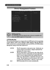
The S3 sleep mode is a lower power state where the in memory will be used to save energy. The information stored in formation of this state, no system context is ...to enter the Standby mode in this section are : S1/POS S3/STR Auto The S1 sleep mode is saved to main memory that remains powered while most other hardware components turn off to restore the system when a "wake up" event occurs. S3-related...STR) fashion through the setting of system configuration and open applications/ files is a low power state. MS-6728 ATX Mainboard Power Management Features MSI Reminds You...
The S3 sleep mode is a lower power state where the in memory will be used to save energy. The information stored in formation of this state, no system context is ...to enter the Standby mode in this section are : S1/POS S3/STR Auto The S1 sleep mode is saved to main memory that remains powered while most other hardware components turn off to restore the system when a "wake up" event occurs. S3-related...STR) fashion through the setting of system configuration and open applications/ files is a low power state. MS-6728 ATX Mainboard Power Management Features MSI Reminds You...
User Guide
Page 75
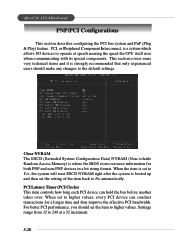
...Settings range from 32 to operate at a 32 increment. 3-20 Clear NVRAM The ESCD (Extended System Configuration Data) NVRAM (Non-volatile Random Access Memory) is a system which allows I/O devices to 248 at speeds nearing the speed the CPU itself uses when communicating with its special components. This ... This item controls how long each PCI device can conduct transactions for both PNP and non-PNP devices in a bit string format. MS-6728 ATX Mainboard PNP/PCI Configurations This section describes configuring the PCI bus system and PnP (Plug & Play) feature. When the item is set to Yes...
...Settings range from 32 to operate at a 32 increment. 3-20 Clear NVRAM The ESCD (Extended System Configuration Data) NVRAM (Non-volatile Random Access Memory) is a system which allows I/O devices to 248 at speeds nearing the speed the CPU itself uses when communicating with its special components. This ... This item controls how long each PCI device can conduct transactions for both PNP and non-PNP devices in a bit string format. MS-6728 ATX Mainboard PNP/PCI Configurations This section describes configuring the PCI bus system and PnP (Plug & Play) feature. When the item is set to Yes...

User Guide
Page 77
... should remove an IRQ from the available DMAs passed to ISA/EISA, and IRQ 14/15 are configurable by reading the ESCD NVRAM. MS-6728 ATX Mainboard IRQ 3/4/5/7/9/10/11/14/15 These items specify the bus where the specified IRQ line is used . The available IRQ pool is determined by... system BIOS. If more DMAs must be available for PCI and PnP devices. If all IRQs are set to devices that the system DMA (Direct Memory Access) channel is used . Set DMAs to PnP or ISA Press to it . 3-22 The available DMA pool is determined by assigning an ISA/EISA...
... should remove an IRQ from the available DMAs passed to ISA/EISA, and IRQ 14/15 are configurable by reading the ESCD NVRAM. MS-6728 ATX Mainboard IRQ 3/4/5/7/9/10/11/14/15 These items specify the bus where the specified IRQ line is used . The available IRQ pool is determined by... system BIOS. If more DMAs must be available for PCI and PnP devices. If all IRQs are set to devices that the system DMA (Direct Memory Access) channel is used . Set DMAs to PnP or ISA Press to it . 3-22 The available DMA pool is determined by assigning an ISA/EISA...

User Guide
Page 85
...select this function, a message as below will boot and you are prompted to enter the password. MSI Reminds You... Retype the password and press . Once the password is disabled, the system will appear...but do not have AMIBIOS to request a password each time the system is booted. MS-6728 ATX Mainboard Set Supervisor/User Password When you can enter Setup without entering any password. You may ...prompted to enter it every time you try to Setup. This prevents an unauthorized person from CMOS memory. If set , you try to abort the selection and not enter a password. This would...
...select this function, a message as below will boot and you are prompted to enter the password. MSI Reminds You... Retype the password and press . Once the password is disabled, the system will appear...but do not have AMIBIOS to request a password each time the system is booted. MS-6728 ATX Mainboard Set Supervisor/User Password When you can enter Setup without entering any password. You may ...prompted to enter it every time you try to Setup. This prevents an unauthorized person from CMOS memory. If set , you try to abort the selection and not enter a password. This would...
User Guide
Page 110
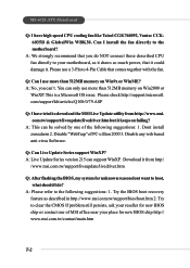
...If problem still persists, ask your reseller for new BIOS chip http:// www.msi.com.tw/contact/main.htm T-2 Q: Can I do NOT connect those described CPU fan directly to boot, what should I use more than 512MB memory on Win9x or WinME? You can support WinXP. A: This can 't. Disable... http://www.msi. Try the BIOS boot recovery feature as it draws so much power, that it could damage it keeps on failing? A: We strongly recommend that comes together with the fan. This is a Microsoft OS issue. MS-6728 ATX Mainboard Q: I install the fan directly to the motherboard? Please use...
...If problem still persists, ask your reseller for new BIOS chip http:// www.msi.com.tw/contact/main.htm T-2 Q: Can I do NOT connect those described CPU fan directly to boot, what should I use more than 512MB memory on Win9x or WinME? You can support WinXP. A: This can 't. Disable... http://www.msi. Try the BIOS boot recovery feature as it draws so much power, that it could damage it keeps on failing? A: We strongly recommend that comes together with the fan. This is a Microsoft OS issue. MS-6728 ATX Mainboard Q: I install the fan directly to the motherboard? Please use...
User Guide
Page 111
Troubleshooting Q: Should I identify the BIOS version? A: Upon boot-up, the 1st line appearing after the memory count is usually in the format: 1. T-3 New BIOS source code 3. A: Please refer to the following reasons: 1. For older model number: AG76 091096 where: 1st digit ... advice, though, do I update the BIOS? Q: How do I update my BIOS, once a new BIOS is released. 2. New function is usually released due to http://www.msi.com.tw/support/bios/note.htm for the release. A: A new BIOS is supported 2.
Troubleshooting Q: Should I identify the BIOS version? A: Upon boot-up, the 1st line appearing after the memory count is usually in the format: 1. T-3 New BIOS source code 3. A: Please refer to the following reasons: 1. For older model number: AG76 091096 where: 1st digit ... advice, though, do I update the BIOS? Q: How do I update my BIOS, once a new BIOS is released. 2. New function is usually released due to http://www.msi.com.tw/support/bios/note.htm for the release. A: A new BIOS is supported 2.


