User Guide
Page 6
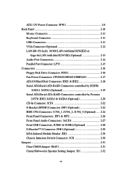
ATX 12V Power Connector: JPW1 2-9 Back Panel 2-10 Mouse Connector 2-11 Keyboard Connector 2-11 USB Connectors 2-11 VGA Connector (Optional 2-12 LAN (RJ-45) Jacks: 10/100 LAN (with Intel 82562EZ) or Giga-bit LAN (with Intel 82547EI) (Optional 2-13 Audio Port Connectors 2-14 Parallel Port... JSP1 (Optional 2-22 IEEE 1394 Connectors: J1394_1, J1394_2, J1394_3 (Optional) ..... 2-24 Front Panel Connectors: JFP1 & JFP2 2-26 Front Panel Audio Connectors: JAUD1 2-27 Front USB Connectors: JUSB1 & JUSB2 (Optional 2-28 D-Bracket™ 2 Connector: JDB1 (Optional 2-29 IrDA Infrared Module ...
ATX 12V Power Connector: JPW1 2-9 Back Panel 2-10 Mouse Connector 2-11 Keyboard Connector 2-11 USB Connectors 2-11 VGA Connector (Optional 2-12 LAN (RJ-45) Jacks: 10/100 LAN (with Intel 82562EZ) or Giga-bit LAN (with Intel 82547EI) (Optional 2-13 Audio Port Connectors 2-14 Parallel Port... JSP1 (Optional 2-22 IEEE 1394 Connectors: J1394_1, J1394_2, J1394_3 (Optional) ..... 2-24 Front Panel Connectors: JFP1 & JFP2 2-26 Front Panel Audio Connectors: JAUD1 2-27 Front USB Connectors: JUSB1 & JUSB2 (Optional 2-28 D-Bracket™ 2 Connector: JDB1 (Optional 2-29 IrDA Infrared Module ...

User Guide
Page 7
... A-1 Installing C-Media Drivers A-2 Hardware Configuration A-4 Software Configuration A-5 Attaching Speakers A-19 Using 2-, 4- Using 4- Slots 2-33 AGP (Accelerated Graphics Port) Slot 2-33 PCI (Peripheral Component Interconnect) Slots 2-33 PCI Interrupt Request Routing 2-34 Chapter 3. or 6-Channel Audio Function A-19 Troubleshooting T-1 Glossary ...G-1 vii BIOS Setup 3-1 Entering Setup 3-2 Selecting the First Boot Device 3-2 Control Keys 3-3 Getting...
... A-1 Installing C-Media Drivers A-2 Hardware Configuration A-4 Software Configuration A-5 Attaching Speakers A-19 Using 2-, 4- Using 4- Slots 2-33 AGP (Accelerated Graphics Port) Slot 2-33 PCI (Peripheral Component Interconnect) Slots 2-33 PCI Interrupt Request Routing 2-34 Chapter 3. or 6-Channel Audio Function A-19 Troubleshooting T-1 Glossary ...G-1 vii BIOS Setup 3-1 Entering Setup 3-2 Selecting the First Boot Device 3-2 Control Keys 3-3 Getting...

User Guide
Page 10
...865G only) (Optional) - 1 parallel port supports SPP/EPP/ECP mode - 8 USB 2.0 ports (Rear * 6/ Front * 2 or Rear * 4/ Front * 4) - 1 Line-In/Line-Out/Mic-In port - 1 RJ45 LAN jack (Optional) - 3 IEEE 1394 pinheaders (Optional) Audio h 6 channels software audio codec C-Media 9739A. - Getting Started ...1 floppy port supports 2 FDDs with 360K, 720K, 1.2M, 1.44M and 2.88Mbytes - 1 serial port COM1, 1 VGA port (for Intel® 82547EI). - Can support SPDIF Out via S-Bracket only. LAN (Optional) h Intel® 82547EI (CSA interface) /Intel® 82562EZ Dual layout. - Dimension h ATX Form Factor...
...865G only) (Optional) - 1 parallel port supports SPP/EPP/ECP mode - 8 USB 2.0 ports (Rear * 6/ Front * 2 or Rear * 4/ Front * 4) - 1 Line-In/Line-Out/Mic-In port - 1 RJ45 LAN jack (Optional) - 3 IEEE 1394 pinheaders (Optional) Audio h 6 channels software audio codec C-Media 9739A. - Getting Started ...1 floppy port supports 2 FDDs with 360K, 720K, 1.2M, 1.44M and 2.88Mbytes - 1 serial port COM1, 1 VGA port (for Intel® 82547EI). - Can support SPDIF Out via S-Bracket only. LAN (Optional) h Intel® 82547EI (CSA interface) /Intel® 82562EZ Dual layout. - Dimension h ATX Form Factor...
User Guide
Page 35
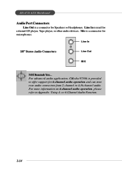
..., Tape player, or other audio devices. Line In is used for 6-channel audio operation and can turn rear audio connectors from 2-channel to 4-/6-channel audio. For advanced audio application, CMedia 9739A is provided to Appendix. Using 4- Mic is a connector for Speakers or Headphones. or 6-Channel Audio Function. 2-14 MS-6728 ATX Mainboard Audio Port Connectors Line Out is a connector...
..., Tape player, or other audio devices. Line In is used for 6-channel audio operation and can turn rear audio connectors from 2-channel to 4-/6-channel audio. For advanced audio application, CMedia 9739A is provided to Appendix. Using 4- Mic is a connector for Speakers or Headphones. or 6-Channel Audio Function. 2-14 MS-6728 ATX Mainboard Audio Port Connectors Line Out is a connector...
User Guide
Page 48
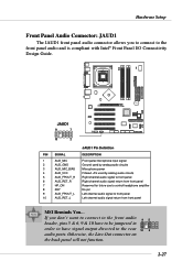
..., pins 5 & 6, 9 & 10 have to be jumpered in order to have signal output directed to the rear 10 6 audio ports. If you to connect to front panel 10 AUD_RET_L Left channel audio signal return from front panel MSI Reminds You... Otherwise, the Line-Out connector on the back panel will not function. 2-27 BATT + JAUD1...
..., pins 5 & 6, 9 & 10 have to be jumpered in order to have signal output directed to the rear 10 6 audio ports. If you to connect to front panel 10 AUD_RET_L Left channel audio signal return from front panel MSI Reminds You... Otherwise, the Line-Out connector on the back panel will not function. 2-27 BATT + JAUD1...
User Guide
Page 80
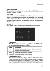
.../COM4 and Disabled. 3-25 If not, the onboard audio controller will automatically determine whether to Disabled. Set Super I /O port addresses of the onboard Serial Port 1 (COM A)/Serial Port 2 (COM B). AC97 Audio Auto allows the motherboard's BIOS to automatically determine the correct base I/O port address. If you 're using any audio device. Selecting Auto allows AMIBIOS to detect whether...
.../COM4 and Disabled. 3-25 If not, the onboard audio controller will automatically determine whether to Disabled. Set Super I /O port addresses of the onboard Serial Port 1 (COM A)/Serial Port 2 (COM B). AC97 Audio Auto allows the motherboard's BIOS to automatically determine the correct base I/O port address. If you 're using any audio device. Selecting Auto allows AMIBIOS to detect whether...

User Manual
Page 6
...the First Boot Device 3-2 vi ATX 12V Power Connector: JPW1 2-9 Back Panel 2-10 Mouse Connector 2-10 Keyboard Connector 2-11 USB Connectors 2-11 Serial Port Connectors: COM A 2-12 RJ-45 LAN Jack: Giga-bit LAN (8110S 2-12 Audio Port Connectors 2-13 Parallel Port Connector: LPT1 2-14 Connectors ... controlled by ICH5: SATA1, SATA2 .... 2-18 D-Bracket™ 2 Connector: JDB1 2-19 IrDA Infrared Module Header: JIR1 2-20 Front Panel Audio Connector: JAUD1 2-20 CD-In Connector: JCD1 2-21 Chassis Intrusion Switch Connector: JCI1 2-21 Front USB Connectors: JUSB1 & JUSB2 2-21 Jumpers...
...the First Boot Device 3-2 vi ATX 12V Power Connector: JPW1 2-9 Back Panel 2-10 Mouse Connector 2-10 Keyboard Connector 2-11 USB Connectors 2-11 Serial Port Connectors: COM A 2-12 RJ-45 LAN Jack: Giga-bit LAN (8110S 2-12 Audio Port Connectors 2-13 Parallel Port Connector: LPT1 2-14 Connectors ... controlled by ICH5: SATA1, SATA2 .... 2-18 D-Bracket™ 2 Connector: JDB1 2-19 IrDA Infrared Module Header: JIR1 2-20 Front Panel Audio Connector: JAUD1 2-20 CD-In Connector: JCD1 2-21 Chassis Intrusion Switch Connector: JCI1 2-21 Front USB Connectors: JUSB1 & JUSB2 2-21 Jumpers...

User Manual
Page 10
... your mainboard specifications. Dimension h ATX Form Factor: 30.5 cm (L) x 24.5 cm (W). Getting Started On-Board Peripherals h On-Board Peripherals include: - 1 floppy port supports 2 FDDs with 360K, 720K, 1.2M, 1.44M and 2.88Mbytes - 1 serial port COMA - 1 parallel port supports SPP/EPP/ECP mode - 8 USB 2.0 ports (Rear * 4/ Front * 4) - 1 Line-In / Line-Out / Mic-In audio port - 1 RJ45 LAN jack - 1 rear...
... your mainboard specifications. Dimension h ATX Form Factor: 30.5 cm (L) x 24.5 cm (W). Getting Started On-Board Peripherals h On-Board Peripherals include: - 1 floppy port supports 2 FDDs with 360K, 720K, 1.2M, 1.44M and 2.88Mbytes - 1 serial port COMA - 1 parallel port supports SPP/EPP/ECP mode - 8 USB 2.0 ports (Rear * 4/ Front * 4) - 1 Line-In / Line-Out / Mic-In audio port - 1 RJ45 LAN jack - 1 rear...

User Manual
Page 33
.... For more information on 6-channel audio operation, please refer to 4-/6-channel audio. or 6-Channel Audio Function. 2-13 SPDIF-out is a connector for microphones. Using 2-, 4- Hardware Setup Audio Port Connectors Line Out is used for external CD player, Tape player, or other audio devices. Line In Line Out S/PDIF Out-Coaxial MIC MSI Reminds You... Line In is...
.... For more information on 6-channel audio operation, please refer to 4-/6-channel audio. or 6-Channel Audio Function. 2-13 SPDIF-out is a connector for microphones. Using 2-, 4- Hardware Setup Audio Port Connectors Line Out is used for external CD player, Tape player, or other audio devices. Line In Line Out S/PDIF Out-Coaxial MIC MSI Reminds You... Line In is...

User Manual
Page 40
... control headphone amplifier 8 KEY No pin 9 AUD_FPOUT_L Left channel audio signal to front panel 10 AUD_RET_L Left channel audio signal return from front panel MSI Reminds You... MS-6728 ATX Mainboard IrDA Infrared Module Header: JIR1 The connector allows you to connect to the rear audio ports. 10 6 Otherwise, the Line-Out connector on the back...
... control headphone amplifier 8 KEY No pin 9 AUD_FPOUT_L Left channel audio signal to front panel 10 AUD_RET_L Left channel audio signal return from front panel MSI Reminds You... MS-6728 ATX Mainboard IrDA Infrared Module Header: JIR1 The connector allows you to connect to the rear audio ports. 10 6 Otherwise, the Line-Out connector on the back...
User Manual
Page 66
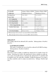
... AC'97 controller will be enabled; Disable the function if you to connect an audio device. Setting options: Disabled, Enabled. AC'97 Audio This item is available for you want to enable or disable the onboard AC'97 (Audio Codec'97) feature. Settings: Disabled and Auto. 3-23 P0-Master / P1-Slave * ... Keep Enabled (not available) (not available) P-ATA Channel Selection Both (not available) Combined Mode Option (not available) * S-ATA 1st Channel / P-ATA 1st Channel S-ATA Ports Definition P0-3rd. / P1-4th. When choosing P-ATA 1st Channel, you can use IDE1, SATA1 & SATA2.
... AC'97 controller will be enabled; Disable the function if you to connect an audio device. Setting options: Disabled, Enabled. AC'97 Audio This item is available for you want to enable or disable the onboard AC'97 (Audio Codec'97) feature. Settings: Disabled and Auto. 3-23 P0-Master / P1-Slave * ... Keep Enabled (not available) (not available) P-ATA Channel Selection Both (not available) Combined Mode Option (not available) * S-ATA 1st Channel / P-ATA 1st Channel S-ATA Ports Definition P0-3rd. / P1-4th. When choosing P-ATA 1st Channel, you can use IDE1, SATA1 & SATA2.
