User Guide
Page 5
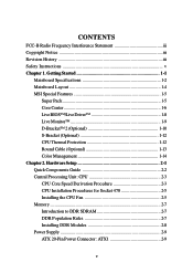
CONTENTS FCC-B Radio Frequency Interference Statement iii Copyright Notice iii Revision History iii Safety Instructions v Chapter 1. Getting Started 1-1 Mainboard Specifications 1-2 Mainboard Layout 1-4 MSI Special Features 1-5 Super Pack 1-5 Core Center 1-6 Live BIOS™/Live Driver 1-8 Live Monitor 1-9 D-Bracket™ 2 (Optional 1-10 S-Bracket (Optional 1-12 ... Procedures for Socket 478 2-5 Installing the CPU Fan 2-5 Memory 2-7 Introduction to DDR SDRAM 2-7 DDR Population Rules 2-7 Installing DDR Modules 2-8 Power Supply 2-9 ATX 20-Pin Power Connector: ATX1 2-9 v
CONTENTS FCC-B Radio Frequency Interference Statement iii Copyright Notice iii Revision History iii Safety Instructions v Chapter 1. Getting Started 1-1 Mainboard Specifications 1-2 Mainboard Layout 1-4 MSI Special Features 1-5 Super Pack 1-5 Core Center 1-6 Live BIOS™/Live Driver 1-8 Live Monitor 1-9 D-Bracket™ 2 (Optional 1-10 S-Bracket (Optional 1-12 ... Procedures for Socket 478 2-5 Installing the CPU Fan 2-5 Memory 2-7 Introduction to DDR SDRAM 2-7 DDR Population Rules 2-7 Installing DDR Modules 2-8 Power Supply 2-9 ATX 20-Pin Power Connector: ATX1 2-9 v
User Guide
Page 6
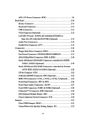
ATX 12V Power Connector: JPW1 2-9 Back Panel 2-10 Mouse Connector 2-11 Keyboard Connector 2-11 USB Connectors 2-11 VGA Connector (Optional 2-12 LAN (RJ-45) Jacks: 10/.../Serial ATA RAID Connectors controlled by ICH5R: SATA1, SATA2 (Optional 2-19 Serial ATA/Serial ATA RAID Connectors controlled by Promise 20378: IDE3, SATA3 & SATA4 (Optional 2-20 CD-In Connector: JCD1 2-22 S-Bracket (SPDIF) Connector: JSP1 (Optional 2-22 IEEE 1394 Connectors: J1394_1, J1394_2, J1394_3 (Optional) ..... 2-24 Front Panel Connectors: JFP1 & JFP2 2-26...
ATX 12V Power Connector: JPW1 2-9 Back Panel 2-10 Mouse Connector 2-11 Keyboard Connector 2-11 USB Connectors 2-11 VGA Connector (Optional 2-12 LAN (RJ-45) Jacks: 10/.../Serial ATA RAID Connectors controlled by ICH5R: SATA1, SATA2 (Optional 2-19 Serial ATA/Serial ATA RAID Connectors controlled by Promise 20378: IDE3, SATA3 & SATA4 (Optional 2-20 CD-In Connector: JCD1 2-22 S-Bracket (SPDIF) Connector: JSP1 (Optional 2-22 IEEE 1394 Connectors: J1394_1, J1394_2, J1394_3 (Optional) ..... 2-24 Front Panel Connectors: JFP1 & JFP2 2-26...

User Guide
Page 7
... Device 3-2 Control Keys 3-3 Getting Help 3-3 The Main Menu 3-4 Standard CMOS Features 3-6 Advanced BIOS Features 3-8 Advanced Chipset Features 3-13 Power Management Features 3-16 PNP/PCI Configurations 3-20 Integrated Peripherals 3-23 PC Health Status 3-27 Frequency/Voltage Control 3-28 Set Supervisor/User Password 3-30 Load High Performance/BIOS Setup Defaults 3-31 Appendix. Using...
... Device 3-2 Control Keys 3-3 Getting Help 3-3 The Main Menu 3-4 Standard CMOS Features 3-6 Advanced BIOS Features 3-8 Advanced Chipset Features 3-13 Power Management Features 3-16 PNP/PCI Configurations 3-20 Integrated Peripherals 3-23 PC Health Status 3-27 Frequency/Voltage Control 3-28 Set Supervisor/User Password 3-30 Load High Performance/BIOS Setup Defaults 3-31 Appendix. Using...
User Guide
Page 30
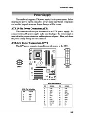
... Power Connector: JPW1 This 12V power connector is inserted in the proper orientation and the pins are aligned. ATX 20-Pin Power Connector: ATX1 This connector allows you to connect to the CPU. 11 1 3 4 1 2 JPW1 20 10 BATT + ATX1 JPW1 Pin Definition PIN SIGNAL 1 GND 2 GND 3 12V 4 12V ATX1 Pin ...PIN SIGNAL PIN 1 3.3V 11 2 3.3V 12 3 GND 13 4 5V 14 5 GND 15 6 5V 16 7 GND 17 8 PW_OK 18 9 5V_SB 19 10 12V 20 SIGNAL 3.3V -12V GND PS_ON GND GND GND -5V 5V 5V 2-9 To connect to ensure that no damage will be caused. Before inserting the power...
... Power Connector: JPW1 This 12V power connector is inserted in the proper orientation and the pins are aligned. ATX 20-Pin Power Connector: ATX1 This connector allows you to connect to the CPU. 11 1 3 4 1 2 JPW1 20 10 BATT + ATX1 JPW1 Pin Definition PIN SIGNAL 1 GND 2 GND 3 12V 4 12V ATX1 Pin ...PIN SIGNAL PIN 1 3.3V 11 2 3.3V 12 3 GND 13 4 5V 14 5 GND 15 6 5V 16 7 GND 17 8 PW_OK 18 9 5V_SB 19 10 12V 20 SIGNAL 3.3V -12V GND PS_ON GND GND GND -5V 5V 5V 2-9 To connect to ensure that no damage will be caused. Before inserting the power...
User Guide
Page 36
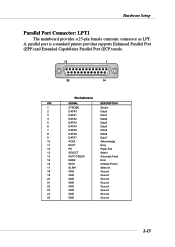
... 13 SELECT Select 14 AUTO FEED# Automatic Feed 15 ERR# Error 16 INIT# Initialize Printer 17 SLIN# Select In 18 GND Ground 19 GND Ground 20 GND Ground 21 GND Ground 22 GND Ground 23 GND Ground 24 GND Ground 25 GND Ground 2-15 Hardware Setup Parallel Port Connector: LPT1 The...
... 13 SELECT Select 14 AUTO FEED# Automatic Feed 15 ERR# Error 16 INIT# Initialize Printer 17 SLIN# Select In 18 GND Ground 19 GND Ground 20 GND Ground 21 GND Ground 22 GND Ground 23 GND Ground 24 GND Ground 25 GND Ground 2-15 Hardware Setup Parallel Port Connector: LPT1 The...
User Guide
Page 41
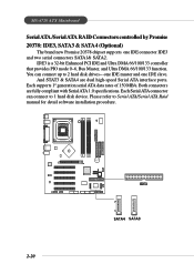
MS-6728 ATX Mainboard Serial ATA /Serial ATA RAID Connectors controlled by Promise 20378: IDE3, SATA3 & SATA4 (Optional) The brand new Promise 20378 chipset supports one IDE slave. ... and one IDE connector IDE3 and two serial connectors SATA1& SATA2. Please refer to Serial ATA/Serial ATA Raid manual for detail software installation procedure. 2-20 B AT T + IDE3 7 1 SATA4 SATA3 IDE3 is a 32-bit Enhanced PCI IDE and Ultra DMA 66/100/133 controller that provides PIO mode 0~6, Bus Master, and...
MS-6728 ATX Mainboard Serial ATA /Serial ATA RAID Connectors controlled by Promise 20378: IDE3, SATA3 & SATA4 (Optional) The brand new Promise 20378 chipset supports one IDE slave. ... and one IDE connector IDE3 and two serial connectors SATA1& SATA2. Please refer to Serial ATA/Serial ATA Raid manual for detail software installation procedure. 2-20 B AT T + IDE3 7 1 SATA4 SATA3 IDE3 is a 32-bit Enhanced PCI IDE and Ultra DMA 66/100/133 controller that provides PIO mode 0~6, Bus Master, and...
User Guide
Page 72
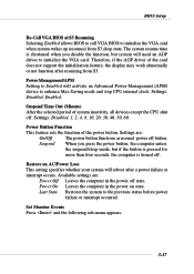
Settings: Disabled, 1, 2, 4, 8, 10, 20, 30, 40, 50, 60. Settings are : Power Off Leaves the computer in the power on AC/Power Loss This setting specifies whether your system will ...
Settings: Disabled, 1, 2, 4, 8, 10, 20, 30, 40, 50, 60. Settings are : Power Off Leaves the computer in the power on AC/Power Loss This setting specifies whether your system will ...
User Guide
Page 75
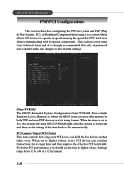
... the system is a system which allows I/O devices to the default settings. For better PCI performance, you should make any changes to operate at a 32 increment. 3-20 Settings range from 32 to No automatically. PCI, or Peripheral Component Interconnect, is booted up and then set the item to higher values, every PCI... device can hold the bus before another takes over. MS-6728 ATX Mainboard PNP/PCI Configurations This section describes configuring the PCI bus system and PnP (Plug & Play) feature.
... the system is a system which allows I/O devices to the default settings. For better PCI performance, you should make any changes to operate at a 32 increment. 3-20 Settings range from 32 to No automatically. PCI, or Peripheral Component Interconnect, is booted up and then set the item to higher values, every PCI... device can hold the bus before another takes over. MS-6728 ATX Mainboard PNP/PCI Configurations This section describes configuring the PCI bus system and PnP (Plug & Play) feature.

User Guide
Page 106
MS-6728 ATX Mainboard 2-Channel Analog Audio Output We recommend that you should still attach the speakers to one Line Out connector of S-Bracket. 5 Coaxial SPDIF jack 6 Line Out (Center and Subwoofer channel, but no functioning in this mode) 7 Line Out (Rear channels) S-Bracket Back Panel 3 4 2 5 6 1 7 A-20 Back Panel 1 MIC 3 2 Line Out (Front...
MS-6728 ATX Mainboard 2-Channel Analog Audio Output We recommend that you should still attach the speakers to one Line Out connector of S-Bracket. 5 Coaxial SPDIF jack 6 Line Out (Center and Subwoofer channel, but no functioning in this mode) 7 Line Out (Rear channels) S-Bracket Back Panel 3 4 2 5 6 1 7 A-20 Back Panel 1 MIC 3 2 Line Out (Front...