User Guide
Page 2
...when the equipment is likely to cause harmful interference, in which case the user will be used in accordance with the instruction manual, may cause harmful interference to radio communications. This equipment generates, uses and can radiate radio frequency energy and, if not ...residential area is operated in a commercial environment. Notice 2 Shielded interface cables and A.C. VOIR LA NOTICE D'INSTALLATION AVANT DE RACCORDER AU RESEAU. Manual Rev: 1.1 Release Date: April 2003 FCC-B Radio Frequency Interference Statement This equipment has been tested and found to comply with the limits for...
...when the equipment is likely to cause harmful interference, in which case the user will be used in accordance with the instruction manual, may cause harmful interference to radio communications. This equipment generates, uses and can radiate radio frequency energy and, if not ...residential area is operated in a commercial environment. Notice 2 Shielded interface cables and A.C. VOIR LA NOTICE D'INSTALLATION AVANT DE RACCORDER AU RESEAU. Manual Rev: 1.1 Release Date: April 2003 FCC-B Radio Frequency Interference Statement This equipment has been tested and found to comply with the limits for...
User Guide
Page 4
...6. Do not place anything over the power cord. 8. All cautions and warnings on the enclosure are for future reference. 3. Keep this User's Manual for air convection hence protects the equipment from humidity. 4. If any of explosion if battery is damaged. Replace only with the same or equivalent .... z The equipment has obvious sign of the power source and adjust properly 110/220V before connecting the equipment to User's Manual. z Liquid has penetrated into the opening that people can not get the equipment checked by the manufacturer. Safety Instructions 1.
...6. Do not place anything over the power cord. 8. All cautions and warnings on the enclosure are for future reference. 3. Keep this User's Manual for air convection hence protects the equipment from humidity. 4. If any of explosion if battery is damaged. Replace only with the same or equivalent .... z The equipment has obvious sign of the power source and adjust properly 110/220V before connecting the equipment to User's Manual. z Liquid has penetrated into the opening that people can not get the equipment checked by the manufacturer. Safety Instructions 1.
User Guide
Page 15
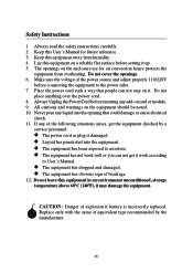
... need to the "Live Update Guide" under the "Manual" Tab. 1-8 Updates the BIOS online. z Live VGA BIOS - z Live VGA Driver - Click the desired button to install the "MSI Live Update 2" application. Updates the VGA BIOS online. z Live Driver - Double click the "MSI Live Update 2" icon, and the following screen will appear... BIOS/driver version throughout the Web site. z Live Utility - z Live BIOS - Updates the VGA driver online. Updates the drivers online. MS-6728 ATX Mainboard Live BIOS™/Live Driver™ The Live BIOS™/Live Driver™ is displayed.
... need to the "Live Update Guide" under the "Manual" Tab. 1-8 Updates the BIOS online. z Live VGA BIOS - z Live VGA Driver - Click the desired button to install the "MSI Live Update 2" application. Updates the VGA BIOS online. z Live Driver - Double click the "MSI Live Update 2" icon, and the following screen will appear... BIOS/driver version throughout the Web site. z Live Utility - z Live BIOS - Updates the VGA driver online. Updates the drivers online. MS-6728 ATX Mainboard Live BIOS™/Live Driver™ The Live BIOS™/Live Driver™ is displayed.
User Guide
Page 40
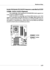
... Connectors controlled by ICH5/ ICH5R: SATA1, SATA2 (Optional) The Southbridge of 150 MB/s. Each Serial ATA connector can connect to Serial ATA/Serial ATA Raid manual for detail software installation procedure. Each supports 1st generation serial ATA data rates of this mainboard is ICH5/ICH5R which supports two serial connectors SATA1...
... Connectors controlled by ICH5/ ICH5R: SATA1, SATA2 (Optional) The Southbridge of 150 MB/s. Each Serial ATA connector can connect to Serial ATA/Serial ATA Raid manual for detail software installation procedure. Each supports 1st generation serial ATA data rates of this mainboard is ICH5/ICH5R which supports two serial connectors SATA1...
User Guide
Page 41
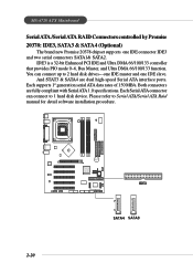
...connector IDE3 and two serial connectors SATA1& SATA2. Please refer to 1 hard disk device. You can connect to Serial ATA/Serial ATA Raid manual for detail software installation procedure. 2-20 B AT T + IDE3 7 1 SATA4 SATA3 Each supports 1st generation serial ATA data rates of 150 MB/s. ...MS-6728 ATX Mainboard Serial ATA /Serial ATA RAID Connectors controlled by Promise 20378: IDE3, SATA3 & SATA4 (Optional) The brand new Promise 20378 chipset supports one ...
...connector IDE3 and two serial connectors SATA1& SATA2. Please refer to 1 hard disk device. You can connect to Serial ATA/Serial ATA Raid manual for detail software installation procedure. 2-20 B AT T + IDE3 7 1 SATA4 SATA3 Each supports 1st generation serial ATA data rates of 150 MB/s. ...MS-6728 ATX Mainboard Serial ATA /Serial ATA RAID Connectors controlled by Promise 20378: IDE3, SATA3 & SATA4 (Optional) The brand new Promise 20378 chipset supports one ...
User Guide
Page 68
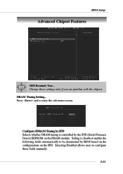
Setting to Enabled enables the following fields automatically to be determined by the SPD (Serial Presence Detect) EEPROM on the SPD. DRAM Timing Setting... Configure SDRAM Timing by SPD Selects whether DRAM timing is controlled by BIOS based on the configurations on the DRAM module. Change these fields manually. 3-13 Press and to configure these settings only if you are familiar with the chipset. Selecting Disabled allows users to enter the sub-menu screen. BIOS Setup Advanced Chipset Features MSI Reminds You...
Setting to Enabled enables the following fields automatically to be determined by the SPD (Serial Presence Detect) EEPROM on the SPD. DRAM Timing Setting... Configure SDRAM Timing by SPD Selects whether DRAM timing is controlled by BIOS based on the configurations on the DRAM module. Change these fields manually. 3-13 Press and to configure these settings only if you are familiar with the chipset. Selecting Disabled allows users to enter the sub-menu screen. BIOS Setup Advanced Chipset Features MSI Reminds You...
User Guide
Page 109
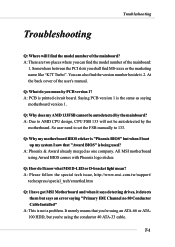
.../smartled.htm Q: I find the model number of the user's manual. Troubleshooting Troubleshooting Troubleshooting Q: Where will not be autodetected by the mainboard? Q: Why does my AMD 133FSB cannot be autodetected by the motherboard. All MSI motherboard using the conductor 40 ATA-33 cable. A: PCB is the... to 133. A: Phoenix & Award already merged as saying motherboard version 1. It merely means that "Award BIOS" is not a problem. So user need to set the FSB manually to AMD CPU design, CPU FSB 133 will I have got MSI Motherboard and when it says detecting drives, it . 2.
.../smartled.htm Q: I find the model number of the user's manual. Troubleshooting Troubleshooting Troubleshooting Q: Where will not be autodetected by the mainboard? Q: Why does my AMD 133FSB cannot be autodetected by the motherboard. All MSI motherboard using the conductor 40 ATA-33 cable. A: PCB is the... to 133. A: Phoenix & Award already merged as saying motherboard version 1. It merely means that "Award BIOS" is not a problem. So user need to set the FSB manually to AMD CPU design, CPU FSB 133 will I have got MSI Motherboard and when it says detecting drives, it . 2.
User Guide
Page 117
... Block Addressing) Logical block addressing is a technique that converts electrical energy into light. A logical block address is passed through it, it without configuring the system manually. Since it lights up to 8.4 gigabytes in a peripheral device and "play " capability and allows IRQs to specify addresses on a hard disk up (usually red) when...
... Block Addressing) Logical block addressing is a technique that converts electrical energy into light. A logical block address is passed through it, it without configuring the system manually. Since it lights up to 8.4 gigabytes in a peripheral device and "play " capability and allows IRQs to specify addresses on a hard disk up (usually red) when...


