User Guide
Page 5
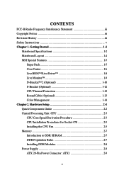
... Guide 2-2 Central Processing Unit: CPU 2-3 CPU Core Speed Derivation Procedure 2-3 CPU Installation Procedures for Socket 478 2-5 Installing the CPU Fan 2-5 Memory 2-7 Introduction to DDR SDRAM 2-7 DDR Population Rules 2-7 Installing DDR Modules 2-8 Power Supply 2-9 ATX ...20-Pin Power Connector: ATX1 2-9 v CONTENTS FCC-B Radio Frequency Interference Statement iii Copyright Notice iii Revision History iii Safety Instructions v Chapter 1. Getting Started 1-1 Mainboard Specifications 1-2 Mainboard Layout 1-4 MSI Special Features 1-5 Super ...
... Guide 2-2 Central Processing Unit: CPU 2-3 CPU Core Speed Derivation Procedure 2-3 CPU Installation Procedures for Socket 478 2-5 Installing the CPU Fan 2-5 Memory 2-7 Introduction to DDR SDRAM 2-7 DDR Population Rules 2-7 Installing DDR Modules 2-8 Power Supply 2-9 ATX ...20-Pin Power Connector: ATX1 2-9 v CONTENTS FCC-B Radio Frequency Interference Statement iii Copyright Notice iii Revision History iii Safety Instructions v Chapter 1. Getting Started 1-1 Mainboard Specifications 1-2 Mainboard Layout 1-4 MSI Special Features 1-5 Super ...
User Guide
Page 15
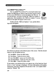
...message is a tool used to detect and update your BIOS/drivers online so that you don't need to the "Live Update Guide" under the "Manual" Tab. 1-8 Double click the "MSI Live Update 2" icon, and the following screen will appear on the screen. Updates the VGA BIOS online. To use the ... are placed on the update instructions, insert the companion CD and refer to install the "MSI Live Update 2" application. If the product you need to start the update process. z Live Utility - MS-6728 ATX Mainboard Live BIOS™/Live Driver™ The Live BIOS™/Live Driver™ is ...
...message is a tool used to detect and update your BIOS/drivers online so that you don't need to the "Live Update Guide" under the "Manual" Tab. 1-8 Double click the "MSI Live Update 2" icon, and the following screen will appear on the screen. Updates the VGA BIOS online. To use the ... are placed on the update instructions, insert the companion CD and refer to install the "MSI Live Update 2" application. If the product you need to start the update process. z Live Utility - MS-6728 ATX Mainboard Live BIOS™/Live Driver™ The Live BIOS™/Live Driver™ is ...
User Guide
Page 47
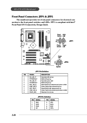
MS-6728 ATX Mainboard Front Panel Connectors: JFP1 & JFP2 The mainboard provides two front panel connectors for electrical connection to GND Reserved. JFP1 is compliant with Intel® Front Panel I/O Connectivity Design Guide. 2-26 Reset HDD Switch LED 9 10 1 2 JFP1 Power Power Switch LED B ATT + Power LED 7 8 1 2 JFP2 Speaker JFP1 Pin Definition PIN...
MS-6728 ATX Mainboard Front Panel Connectors: JFP1 & JFP2 The mainboard provides two front panel connectors for electrical connection to GND Reserved. JFP1 is compliant with Intel® Front Panel I/O Connectivity Design Guide. 2-26 Reset HDD Switch LED 9 10 1 2 JFP1 Power Power Switch LED B ATT + Power LED 7 8 1 2 JFP2 Speaker JFP1 Pin Definition PIN...
User Guide
Page 48
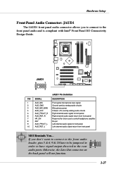
... 4 AUD_VCC Filtered +5V used by analog audio circuits 5 AUD_FPOUT_R Right channel audio signal to front panel 6 AUD_RET_R Right channel audio signal return from front panel MSI Reminds You... Otherwise, the Line-Out connector on the back panel will not function. 2-27 Hardware Setup Front Panel Audio Connector: JAUD1 The JAUD1 front... headphone amplifier 8 KEY No pin 9 AUD_FPOUT_L Left channel audio signal to the front panel audio and is compliant with Intel® Front Panel I/O Connectivity Design Guide.
... 4 AUD_VCC Filtered +5V used by analog audio circuits 5 AUD_FPOUT_R Right channel audio signal to front panel 6 AUD_RET_R Right channel audio signal return from front panel MSI Reminds You... Otherwise, the Line-Out connector on the back panel will not function. 2-27 Hardware Setup Front Panel Audio Connector: JAUD1 The JAUD1 front... headphone amplifier 8 KEY No pin 9 AUD_FPOUT_L Left channel audio signal to the front panel audio and is compliant with Intel® Front Panel I/O Connectivity Design Guide.
User Guide
Page 49
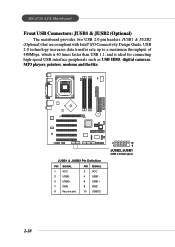
... SIGNAL PIN SIGNAL 1 VCC 2 VCC 3 USB0- 4 USB1- 5 USB0+ 6 USB1+ 7 GND 8 GND 9 Key (no pin) 10 USBOC 2 10 1 9 JUSB2, JUSB1 (USB 2.0/Intel spec) 2-28 MS-6728 ATX Mainboard Front USB Connectors: JUSB1 & JUSB2 (Optional) The mainboard provides two USB 2.0 pin headers JUSB1 & JUSB2 (Optional) that are compliant with Intel® I/O Connectivity Design...
... SIGNAL PIN SIGNAL 1 VCC 2 VCC 3 USB0- 4 USB1- 5 USB0+ 6 USB1+ 7 GND 8 GND 9 Key (no pin) 10 USBOC 2 10 1 9 JUSB2, JUSB1 (USB 2.0/Intel spec) 2-28 MS-6728 ATX Mainboard Front USB Connectors: JUSB1 & JUSB2 (Optional) The mainboard provides two USB 2.0 pin headers JUSB1 & JUSB2 (Optional) that are compliant with Intel® I/O Connectivity Design...
User Guide
Page 51
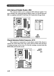
You must enter the BIOS utility and clear the record. The system will be short. MS-6728 ATX Mainboard IrDA Infrared Module Header: JIR1 The connector allows you must configure the setting through the BIOS setup to use the IR function. To clear ... record this status and show a warning message on the screen. GND 2 CINTRU 1 JCI1 BATT + 2-30 JIR1 is compliant with Intel® Front Panel I/O Connectivity Design Guide.
You must enter the BIOS utility and clear the record. The system will be short. MS-6728 ATX Mainboard IrDA Infrared Module Header: JIR1 The connector allows you must configure the setting through the BIOS setup to use the IR function. To clear ... record this status and show a warning message on the screen. GND 2 CINTRU 1 JCI1 BATT + 2-30 JIR1 is compliant with Intel® Front Panel I/O Connectivity Design Guide.
User Guide
Page 67
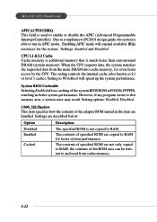
... ROM area can be written to and read from the main DRAM into cache memory, for faster system performance. Due to compliance to PC2001 design guide, the system is much faster than conventional DRAM (system memory). Settings: Enabled and Disabled. CPU L1 & L2 Cache Cache memory is additional memory... Enabling APIC mode will speed up the system performance. The setting controls the internal cache (also known as L1 or level 1 cache). MS-6728 ATX Mainboard APIC ACPI SCI IRQ This field is not copied to RAM. However, if any program writes to this memory area, a system error may result...
... ROM area can be written to and read from the main DRAM into cache memory, for faster system performance. Due to compliance to PC2001 design guide, the system is much faster than conventional DRAM (system memory). Settings: Enabled and Disabled. CPU L1 & L2 Cache Cache memory is additional memory... Enabling APIC mode will speed up the system performance. The setting controls the internal cache (also known as L1 or level 1 cache). MS-6728 ATX Mainboard APIC ACPI SCI IRQ This field is not copied to RAM. However, if any program writes to this memory area, a system error may result...
