
User Guide
Page 8
... Frequency Interference Statement iv WEEE (Waste Electrical and Electronic Equipment) Statement v English En-1 Mainboard Specifications En-2 Quick Components Guide En-4 CPU (Central Processing Unit En-5 Memory En-8 Power Supply En-10 Back Panel En-11 Connectors En-12 Switch En-17 Jumpers En-18 Slots En-19 LED Status Indicators En...
... Frequency Interference Statement iv WEEE (Waste Electrical and Electronic Equipment) Statement v English En-1 Mainboard Specifications En-2 Quick Components Guide En-4 CPU (Central Processing Unit En-5 Memory En-8 Power Supply En-10 Back Panel En-11 Connectors En-12 Switch En-17 Jumpers En-18 Slots En-19 LED Status Indicators En...
User Guide
Page 12
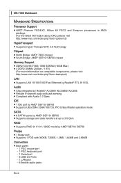
...Phenom FX/X4/X2, Althon 64 FX/X2 and Sempron processors in AM2+ package (For the latest information about CPU, please visit http://www.msi.com/index.php?func=cpuform2) HyperTransport ■ Supports Hyper Transport(HT) 3.0 Technology Chipset ■ North Bridge: AMD® 790X chipset ...■ South Bridge: AMD® SB710/ SB700 chipset Memory Support ■ DDR2 533/ 667/ 800/ 1066 SDRAM (16GB Max) ■ 4 DDR2 DIMMs (240pin / 1.8V) (For more information on compatible components...
...Phenom FX/X4/X2, Althon 64 FX/X2 and Sempron processors in AM2+ package (For the latest information about CPU, please visit http://www.msi.com/index.php?func=cpuform2) HyperTransport ■ Supports Hyper Transport(HT) 3.0 Technology Chipset ■ North Bridge: AMD® 790X chipset ...■ South Bridge: AMD® SB710/ SB700 chipset Memory Support ■ DDR2 533/ 667/ 800/ 1066 SDRAM (16GB Max) ■ 4 DDR2 DIMMs (240pin / 1.8V) (For more information on compatible components...
User Guide
Page 18
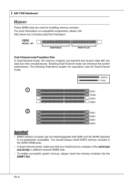
... more information on compatible components, please visit http://www.msi.com/index.php?func=testreport DDR2 240-pin, 1.8V 64x2=128 pin 56x2=112 pin Dual-Channel mode Population Rule In Dual-Channel mode, the memory modules can enhance the system performance. Enabling Dual-Channel ...backwards compatible. The following illustrations explain the population rules for installing memory modules. You should always install DDR2 memory modules in the DDR2 DIMM slots. • In Dual-Channel mode, make sure that you install memory modules of the same type and density in different channel DIMM...
... more information on compatible components, please visit http://www.msi.com/index.php?func=testreport DDR2 240-pin, 1.8V 64x2=128 pin 56x2=112 pin Dual-Channel mode Population Rule In Dual-Channel mode, the memory modules can enhance the system performance. Enabling Dual-Channel ...backwards compatible. The following illustrations explain the population rules for installing memory modules. You should always install DDR2 memory modules in the DDR2 DIMM slots. • In Dual-Channel mode, make sure that you install memory modules of the same type and density in different channel DIMM...
User Guide
Page 19
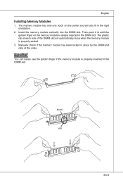
... vertically into the DIMM slot. Important You can barely see the golden finger if the memory module is properly inserted in the DIMM slot. Manually check if the memory module has been locked in the right orientation. 2. Then push it in until the golden finger on the center and will only... place by the DIMM slot clips at each side of the DIMM slot will automatically close when the memory module is deeply inserted in the DIMM slot. The memory module has only one notch on the memory module is properly seated. 3. The plastic clip at the sides. Notch Volt En-9 English Installing...
... vertically into the DIMM slot. Important You can barely see the golden finger if the memory module is properly inserted in the DIMM slot. Manually check if the memory module has been locked in the right orientation. 2. Then push it in until the golden finger on the center and will only... place by the DIMM slot clips at each side of the DIMM slot will automatically close when the memory module is deeply inserted in the DIMM slot. The memory module has only one notch on the memory module is properly seated. 3. The plastic clip at the sides. Notch Volt En-9 English Installing...
User Guide
Page 31
... = all standard customers. English BIOS Setup This chapter provides basic information on the screen during the system booting up , the 1st line appearing after the memory count is usually in this BIOS was released.
... = all standard customers. English BIOS Setup This chapter provides basic information on the screen during the system booting up , the 1st line appearing after the memory count is usually in this BIOS was released.
User Guide
Page 36
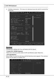
Read-only. ▶ CPU Specifications Press to overclock the mainboard. This submenu shows the information of CPU and Memory speed. ▍ MS-7388 Mainboard 4. Cell Menu Introduction : This menu is for advanced user who want to enter the sub-menu and the following screen appears. Important Change these settings only if you are familiar with the chipset. ▶ Current CPU / DRAM Frequency These items show the current clocks of installed CPU. En-26
Read-only. ▶ CPU Specifications Press to overclock the mainboard. This submenu shows the information of CPU and Memory speed. ▍ MS-7388 Mainboard 4. Cell Menu Introduction : This menu is for advanced user who want to enter the sub-menu and the following screen appears. Important Change these settings only if you are familiar with the chipset. ▶ Current CPU / DRAM Frequency These items show the current clocks of installed CPU. En-26
User Guide
Page 38
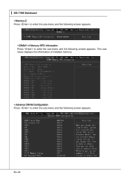
En-28 ▍ MS-7388 Mainboard ▶ Memory-Z Press to enter the sub-menu and the following screen appears. ▶ DIMM1~4 Memory SPD Information Press to enter the sub-menu and the following screen appears. This submenu displays the information of installed memory. ▶ Advance DRAM Configuration Press to enter the sub-menu and the following screen appears.
En-28 ▍ MS-7388 Mainboard ▶ Memory-Z Press to enter the sub-menu and the following screen appears. ▶ DIMM1~4 Memory SPD Information Press to enter the sub-menu and the following screen appears. This submenu displays the information of installed memory. ▶ Advance DRAM Configuration Press to enter the sub-menu and the following screen appears.
User Guide
Page 39
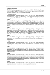
... adjustable. This setting determines the time RAS takes to read from row activation up to the precharging of clock cycles a memory row takes to complete a full cycle, from and write to a memory cell. ▶ tRTP When the DRAM Timing Mode sets to [DCT 0], [DCT1] or [Both], the field is allowed ... allows you set this field to precharge. En-29 This setting controls the number of delay (in the write buffers can be written to the memory cells before DRAM refresh may be allowed to [DCT 0], [DCT 1] or [Both], some fields will appear and selectable. This delay is required to ...
... adjustable. This setting determines the time RAS takes to read from row activation up to the precharging of clock cycles a memory row takes to complete a full cycle, from and write to a memory cell. ▶ tRTP When the DRAM Timing Mode sets to [DCT 0], [DCT1] or [Both], the field is allowed ... allows you set this field to precharge. En-29 This setting controls the number of delay (in the write buffers can be written to the memory cells before DRAM refresh may be allowed to [DCT 0], [DCT 1] or [Both], some fields will appear and selectable. This delay is required to ...

User Guide
Page 40
...the field is adjustable. This field controls the SDRAM command rate. Selecting [1T] makes SDRAM signal controller to adjust the voltage of CPU, Memory and chipset. ▶ Spread Spectrum When the mainboard's clock generator pulses, the extreme values (spikes) of the pulses are overclocking because even ...a slight jitter can introduce a temporary boost in MHz). ▶ Auto Disable DRAM/PCI Frequency When set to Read Command Delay memory timing. Setting to [Auto], the system will detect the HT link speed automatically. ▶ Adjust PCI-E Frequency (MHz) This field ...
...the field is adjustable. This field controls the SDRAM command rate. Selecting [1T] makes SDRAM signal controller to adjust the voltage of CPU, Memory and chipset. ▶ Spread Spectrum When the mainboard's clock generator pulses, the extreme values (spikes) of the pulses are overclocking because even ...a slight jitter can introduce a temporary boost in MHz). ▶ Auto Disable DRAM/PCI Frequency When set to Read Command Delay memory timing. Setting to [Auto], the system will detect the HT link speed automatically. ▶ Adjust PCI-E Frequency (MHz) This field ...


