User Guide
Page 2
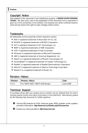
... MSI website for FAQ, technical guide, BIOS updates, driver updates, and other information: http://www.msi.com/index.php?func=service ◙ Contact our technical staff at: http://ocss.msi.com ii ▍ Preface Copyright Notice The material in the preparation of MICRO-STAR INTERNATIONAL. Revision History Revision V1.2 Revision History For 790XT-G45 / 790XT-G35 Europe Date June 2009 Technical Support If a problem...
... MSI website for FAQ, technical guide, BIOS updates, driver updates, and other information: http://www.msi.com/index.php?func=service ◙ Contact our technical staff at: http://ocss.msi.com ii ▍ Preface Copyright Notice The material in the preparation of MICRO-STAR INTERNATIONAL. Revision History Revision V1.2 Revision History For 790XT-G45 / 790XT-G35 Europe Date June 2009 Technical Support If a problem...
User Guide
Page 3
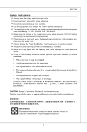
..., waste batteries should be collected separately for recycleing special disposal. iii thing over the power cord. ■ Always Unplug the Power Cord before inserting any add-on card or module...instructions carefully. ■ Keep this User's Manual for future reference. ■ Keep this equipment away from overheating. DO NOT LEAVE THIS EQUIPMENT IN AN ENVIRONMENT UNCONDITIONED, STORAGE TEMPERATURE ABOVE 600 C (1400F), IT MAY DAMAGE THE EQUIPMENT. Replace only with the same or equivalent type recommended by service personnel: ◯ The power cord or plug is incorrectly replaced...
..., waste batteries should be collected separately for recycleing special disposal. iii thing over the power cord. ■ Always Unplug the Power Cord before inserting any add-on card or module...instructions carefully. ■ Keep this User's Manual for future reference. ■ Keep this equipment away from overheating. DO NOT LEAVE THIS EQUIPMENT IN AN ENVIRONMENT UNCONDITIONED, STORAGE TEMPERATURE ABOVE 600 C (1400F), IT MAY DAMAGE THE EQUIPMENT. Replace only with the same or equivalent type recommended by service personnel: ◯ The power cord or plug is incorrectly replaced...

User Guide
Page 8
... History ii Technical Support ii Safety Instructions iii FCC-B Radio Frequency Interference Statement iv WEEE (Waste Electrical and Electronic Equipment) Statement v English En-1 Mainboard Specifications En-2 Quick Components Guide En-4 CPU (Central Processing Unit En-5 Memory En-8 Power Supply En-10 Back Panel En-11 Connectors En-12 Switch En-17 Jumpers En-18 Slots En-19 LED Status Indicators En-20 BIOS Setup En-21 Software Information En...
... History ii Technical Support ii Safety Instructions iii FCC-B Radio Frequency Interference Statement iv WEEE (Waste Electrical and Electronic Equipment) Statement v English En-1 Mainboard Specifications En-2 Quick Components Guide En-4 CPU (Central Processing Unit En-5 Memory En-8 Power Supply En-10 Back Panel En-11 Connectors En-12 Switch En-17 Jumpers En-18 Slots En-19 LED Status Indicators En-20 BIOS Setup En-21 Software Information En...
User Guide
Page 12
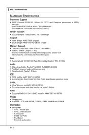
... 1.0 Spec IDE ■ 1 IDE port by AMD® SB710/ SB700 ■ Supports Ultra DMA 33/66/100/133, PIO & Bus Master operation mode SATA ■ 6 SATAII ports by AMD® SB710/ SB700 ■ Supports storage and data transfers at up to 3.0 Gb/s RAID ■ Supports RAID 0/ 1/ 0+1/ JBOD mode by AMD® SB710/ SB700 Floppy ■ 1 floppy port ■ Supports 1 FDD with 360KB, 720KB, 1.2MB, 1.44MB and 2.88MB Connectors ■ Back panel - 1 PS/2 mouse port - 1 PS/2 keyboard port - 1 Serial port - 6 USB 2.0 Ports - 1 LAN...
... 1.0 Spec IDE ■ 1 IDE port by AMD® SB710/ SB700 ■ Supports Ultra DMA 33/66/100/133, PIO & Bus Master operation mode SATA ■ 6 SATAII ports by AMD® SB710/ SB700 ■ Supports storage and data transfers at up to 3.0 Gb/s RAID ■ Supports RAID 0/ 1/ 0+1/ JBOD mode by AMD® SB710/ SB700 Floppy ■ 1 floppy port ■ Supports 1 FDD with 360KB, 720KB, 1.2MB, 1.44MB and 2.88MB Connectors ■ Back panel - 1 PS/2 mouse port - 1 PS/2 keyboard port - 1 Serial port - 6 USB 2.0 Ports - 1 LAN...

User Guide
Page 13
English ■ On-Board Connectors - 3 USB 2.0 connectors - 1 Chassis Intrusion connector - 1 CD-In connector - 1 Front Panel Audio connector - 1 SPDIF-Out connector - 1 TPM connector (optional) - 1 OC switch Slots ■ 2 PCI Express x16 slot ■ 2 PCI Express x1 slot ■ 2 PCI slots, support 3.3V/ 5V PCI bus Interface Form Factor ■ ATX (30.5cm X 21.0 cm) Mounting ■ 6 mounting holes (If you need to purchase accessories and request the part numbers, you could search the product web page and find details on our web address below http://www.msi.com/index.php) En-3
English ■ On-Board Connectors - 3 USB 2.0 connectors - 1 Chassis Intrusion connector - 1 CD-In connector - 1 Front Panel Audio connector - 1 SPDIF-Out connector - 1 TPM connector (optional) - 1 OC switch Slots ■ 2 PCI Express x16 slot ■ 2 PCI Express x1 slot ■ 2 PCI slots, support 3.3V/ 5V PCI bus Interface Form Factor ■ ATX (30.5cm X 21.0 cm) Mounting ■ 6 mounting holes (If you need to purchase accessories and request the part numbers, you could search the product web page and find details on our web address below http://www.msi.com/index.php) En-3
User Guide
Page 15
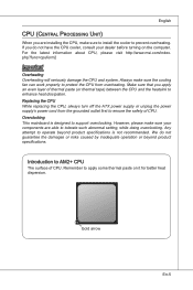
... surface of thermal paste (or thermal tape) between the CPU and the heatsink to apply some thermal paste on the computer. For the latest information about CPU, please visit http://www.msi.com/index. Replacing the CPU While replacing the CPU, always turn off the ATX power supply or unplug the power supply's power cord from overheating. php?func=cpuform2 Important Overheating Overheating will seriously...
... surface of thermal paste (or thermal tape) between the CPU and the heatsink to apply some thermal paste on the computer. For the latest information about CPU, please visit http://www.msi.com/index. Replacing the CPU While replacing the CPU, always turn off the ATX power supply or unplug the power supply's power cord from overheating. php?func=cpuform2 Important Overheating Overheating will seriously...
User Guide
Page 18
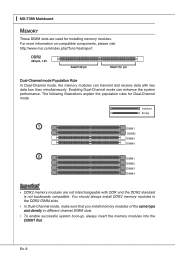
... on compatible components, please visit http://www.msi.com/index.php?func=testreport DDR2 240-pin, 1.8V 64x2=128 pin 56x2=112 pin Dual-Channel mode Population Rule In Dual-Channel mode, the memory modules can enhance the system performance. The following illustrations explain the population rules for installing memory modules. ▍ MS-7388 Mainboard Memory These DIMM slots are not interchangeable with two data bus lines simultaneously. Enabling Dual-Channel mode...
... on compatible components, please visit http://www.msi.com/index.php?func=testreport DDR2 240-pin, 1.8V 64x2=128 pin 56x2=112 pin Dual-Channel mode Population Rule In Dual-Channel mode, the memory modules can enhance the system performance. The following illustrations explain the population rules for installing memory modules. ▍ MS-7388 Mainboard Memory These DIMM slots are not interchangeable with two data bus lines simultaneously. Enabling Dual-Channel mode...

User Guide
Page 20
... used to provide power to the CPU. 2.G1.rGouronudnd 4.+31.+21V2V Important • Make sure that all the connectors are connected to proper ATX power supplies to connect an ATX 24-pin power supply. To connect the ATX 24-pin power supply, make sure the plug of 350 watts (and above) is inserted in the proper orientation and the pins are aligned. If you to ensure stable operation of the mainboard...
... used to provide power to the CPU. 2.G1.rGouronudnd 4.+31.+21V2V Important • Make sure that all the connectors are connected to proper ATX power supplies to connect an ATX 24-pin power supply. To connect the ATX 24-pin power supply, make sure the plug of 350 watts (and above) is inserted in the proper orientation and the pins are aligned. If you to ensure stable operation of the mainboard...
User Guide
Page 22
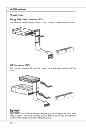
...you install two IDE devices on the same cable, you must configure the drives separately to IDE device's documentation supplied by setting jumpers. En-12 ▍ MS-7388 Mainboard Connectors Floppy Disk Drive Connector: FDD1 This connector supports 360KB, 720KB, 1.2MB, 1.44MB or 2.88MB floppy disk drive. Fl opMpySDI Kdkldkddfkkakfskkdskkdakaddfdddffdfkad-dkdffdldkddjadfdsdddjfdddffkadasdfdddffdfadasfsadfddsddadasdsaddsdafsddadsdddfdsadddfffaffsfsdasfdfffdf 5 D 1i s/k4"DFr il voeppCyonnect or 3 1/2" F l oppy D i sk D r i ve Connector 3 1/2" F l oppy D i sk D ri ve Connector IDE Connector...
...you install two IDE devices on the same cable, you must configure the drives separately to IDE device's documentation supplied by setting jumpers. En-12 ▍ MS-7388 Mainboard Connectors Floppy Disk Drive Connector: FDD1 This connector supports 360KB, 720KB, 1.2MB, 1.44MB or 2.88MB floppy disk drive. Fl opMpySDI Kdkldkddfkkakfskkdskkdakaddfdddffdfkad-dkdffdldkddjadfdsdddjfdddffkadasdfdddffdfadasfsadfddsddadasdsaddsdafsddadsdddfdsadddfffaffsfsdasfdfffdf 5 D 1i s/k4"DFr il voeppCyonnect or 3 1/2" F l oppy D i sk D r i ve Connector 3 1/2" F l oppy D i sk D ri ve Connector IDE Connector...

User Guide
Page 24
... Mainboard Fan Power Connectors: CPUFAN, SYSFAN1, SYS_FAN2 The fan power connectors support system cooling fan with 3 or 4 pins power connector are both available for CPUFAN Chassis Intrusion Connector: JCI1 This connector connects to the chassis intrusion switch cable. CPUFAN SYSFAN1/ SYS_FAN2 4.3C.oS2n.e+1tnr1.osG2lorVround 3.S2.e+1n1.sG2orVround Important • Please refer to the actual CPU temperature. • Fan cooler set with +12V. If the mainboard has a System Hardware Monitor chipset on-board, you must use a specially designed fan...
... Mainboard Fan Power Connectors: CPUFAN, SYSFAN1, SYS_FAN2 The fan power connectors support system cooling fan with 3 or 4 pins power connector are both available for CPUFAN Chassis Intrusion Connector: JCI1 This connector connects to the chassis intrusion switch cable. CPUFAN SYSFAN1/ SYS_FAN2 4.3C.oS2n.e+1tnr1.osG2lorVround 3.S2.e+1n1.sG2orVround Important • Please refer to the actual CPU temperature. • Fan cooler set with +12V. If the mainboard has a System Hardware Monitor chipset on-board, you must use a specially designed fan...

User Guide
Page 28
▍ MS-7388 Mainboard Jumpers Clear CMOS Jumper: JBAT1 There is turned on ; With the CMOS RAM, the system can clear CMOS by shorting 2-3 pin while the system is on . En-18 Avoid clearing the CMOS while the system is off. If you want to clear the system configuration, set the jumper to clear data. 1 JBAT1 1 Keep Data 1 Clear Data Important You can automatically boot OS every time it will damage the mainboard. it is a CMOS RAM onboard that has a power supply from an external battery to 1-2 pin position. Then return to keep the data of system configuration.
▍ MS-7388 Mainboard Jumpers Clear CMOS Jumper: JBAT1 There is turned on ; With the CMOS RAM, the system can clear CMOS by shorting 2-3 pin while the system is on . En-18 Avoid clearing the CMOS while the system is off. If you want to clear the system configuration, set the jumper to clear data. 1 JBAT1 1 Keep Data 1 Clear Data Important You can automatically boot OS every time it will damage the mainboard. it is a CMOS RAM onboard that has a power supply from an external battery to 1-2 pin position. Then return to keep the data of system configuration.
User Guide
Page 29
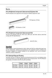
... I-R-Q, are typically connected to the PCI bus pins as jumpers, switches or BIOS configuration. Slots PCI (Peripheral Component Interconnect) Express Slot The PCI Express slot supports the PCI Express interface expansion card. English PCI Express x16 Slot PCI Express x1 Slot PCI (Peripheral Component Interconnect) Slot The PCI slot supports LAN card, SCSI card, USB card, and other add-on cards that comply with PCI specifications. 32-bit PCI Slot Important When adding or removing expansion cards, make sure that you unplug the power supply first. The PCI IRQ pins are hardware lines...
... I-R-Q, are typically connected to the PCI bus pins as jumpers, switches or BIOS configuration. Slots PCI (Peripheral Component Interconnect) Express Slot The PCI Express slot supports the PCI Express interface expansion card. English PCI Express x16 Slot PCI Express x1 Slot PCI (Peripheral Component Interconnect) Slot The PCI slot supports LAN card, SCSI card, USB card, and other add-on cards that comply with PCI specifications. 32-bit PCI Slot Important When adding or removing expansion cards, make sure that you unplug the power supply first. The PCI IRQ pins are hardware lines...
User Guide
Page 31
... the BIOS version. 052109 refers to run the Setup program when: ■ An error message appears on the BIOS Setup program and allows you to run BIOS SETUP. ■ You want to change the default settings for customized features. It is the BIOS version. English BIOS Setup This chapter provides basic information on the screen during the system booting up , the 1st line appearing after the memory count...
... the BIOS version. 052109 refers to run the Setup program when: ■ An error message appears on the BIOS Setup program and allows you to run BIOS SETUP. ■ You want to change the default settings for customized features. It is the BIOS version. English BIOS Setup This chapter provides basic information on the screen during the system booting up , the 1st line appearing after the memory count...

User Guide
Page 32
... Help The BIOS setup program provides a General Help screen. Press DEL to enter SETUP If the message disappears before you respond and you can make changes to select the item. You can use the arrow keys ( ↑↓ ) to . En-22 You may also restart the system by turning it OFF and On or pressing the RESET button. Main Menu The main menu lists the setup functions...
... Help The BIOS setup program provides a General Help screen. Press DEL to enter SETUP If the message disappears before you respond and you can make changes to select the item. You can use the arrow keys ( ↑↓ ) to . En-22 You may also restart the system by turning it OFF and On or pressing the RESET button. Main Menu The main menu lists the setup functions...
User Guide
Page 33
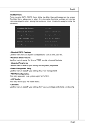
En-23 The Main Menu allows you enter BIOS CMOS Setup Utility, the Main Menu will appear on the screen. English The Main Menu Once you to specify your PC health status. ▶ Cell Menu Use this menu to specify your settings for power management. ▶ PNP/PCI Configurations This entry appears if your system supports PnP/PCI. ▶ H/W Monitor This entry shows your settings for frequency/voltage control and overclocking. Use arrow keys to select among the items and...
En-23 The Main Menu allows you enter BIOS CMOS Setup Utility, the Main Menu will appear on the screen. English The Main Menu Once you to specify your PC health status. ▶ Cell Menu Use this menu to specify your settings for power management. ▶ PNP/PCI Configurations This entry appears if your system supports PnP/PCI. ▶ H/W Monitor This entry shows your settings for frequency/voltage control and overclocking. Use arrow keys to select among the items and...
User Guide
Page 35
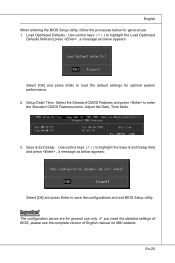
... the configurations and exit BIOS Setup utility. Adjust the Date, Time fields. 3. En-25 English When entering the BIOS Setup utility, follow the processes below for general use only. If you need the detailed settings of BIOS, please see the complete version of English manual on MSI website. Important The configuration above are for optimal system performance. 2. Load Optimized Defaults : Use control keys (↑↓ ) to highlight the Load Optimized Defaults field...
... the configurations and exit BIOS Setup utility. Adjust the Date, Time fields. 3. En-25 English When entering the BIOS Setup utility, follow the processes below for general use only. If you need the detailed settings of BIOS, please see the complete version of English manual on MSI website. Important The configuration above are for optimal system performance. 2. Load Optimized Defaults : Use control keys (↑↓ ) to highlight the Load Optimized Defaults field...
User Guide
Page 36
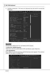
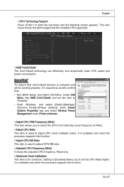
This submenu shows the information of CPU and Memory speed. Read-only. ▶ CPU Specifications Press to overclock the mainboard. Cell Menu Introduction : This menu is for advanced user who want to enter the sub-menu and the following screen appears. Important Change these settings only if you are familiar with the chipset. ▶ Current CPU / DRAM Frequency These items show the current clocks of installed CPU. En-26 ▍ MS-7388 Mainboard 4.
This submenu shows the information of CPU and Memory speed. Read-only. ▶ CPU Specifications Press to overclock the mainboard. Cell Menu Introduction : This menu is for advanced user who want to enter the sub-menu and the following screen appears. Important Change these settings only if you are familiar with the chipset. ▶ Current CPU / DRAM Frequency These items show the current clocks of installed CPU. En-26 ▍ MS-7388 Mainboard 4.
User Guide
Page 37
... Minimal Power Management under Power schemes. ▶ Adjust CPU FSB Frequency (MHz) This item allows you to set this item to "Enabled". • Enter Windows, and select [Start]->[Settings]>[Control Panel]->[Power Options]. Setting to [Enabled] allows you to select the CPU Front Side Bus clock frequency (in MHz). ▶ Adjust CPU Ratio This item is used to adjust CPU clock multiplier (ratio). It is for overclock. This submenu shows the technologies that : • Run BIOS Setup, and...
... Minimal Power Management under Power schemes. ▶ Adjust CPU FSB Frequency (MHz) This item allows you to set this item to "Enabled". • Enter Windows, and select [Start]->[Settings]>[Control Panel]->[Power Options]. Setting to [Enabled] allows you to select the CPU Front Side Bus clock frequency (in MHz). ▶ Adjust CPU Ratio This item is used to adjust CPU clock multiplier (ratio). It is for overclock. This submenu shows the technologies that : • Run BIOS Setup, and...

User Guide
Page 40
... spikes of the pulses are overclocking because even a slight jitter can introduce a temporary boost in MHz). ▶ Auto Disable DRAM/PCI Frequency When set to [Enabled], the system will remove (turn off) clocks from and write to memory cells. ▶ 1T/2T Memory Timing When the DRAM Timing Mode sets to [DCT 0], [DCT1] or [Both], the field is adjustable. This item controls the Write Data In to...
... spikes of the pulses are overclocking because even a slight jitter can introduce a temporary boost in MHz). ▶ Auto Disable DRAM/PCI Frequency When set to [Enabled], the system will remove (turn off) clocks from and write to memory cells. ▶ 1T/2T Memory Timing When the DRAM Timing Mode sets to [DCT 0], [DCT1] or [Both], the field is adjustable. This item controls the Write Data In to...

User Guide
Page 42
... the driver or utility and follow the pop-up screen to get the latest drivers and BIOS for better system performance. Utility menu : The Utility menu shows the software applications that is included in the mainboard package, and place it into the CD-ROM drive. Install the driver by your desire and to activate the device. - ▍ MS-7388 Mainboard Software Information Take out the Driver/Utility CD that the mainboard supports. -
... the driver or utility and follow the pop-up screen to get the latest drivers and BIOS for better system performance. Utility menu : The Utility menu shows the software applications that is included in the mainboard package, and place it into the CD-ROM drive. Install the driver by your desire and to activate the device. - ▍ MS-7388 Mainboard Software Information Take out the Driver/Utility CD that the mainboard supports. -


