User Guide
Page 10
The 790FX-GD70 Series motherboards are based on AMD® 790FX & SB750 chipset for choosing the 790FX-GD70 Series (MS7577 v1.X) ATX motherboard. Designed to fit the advanced AMD® Phenom II X4/ X3 and Athlon X4/ X3/ X2 AM 3 processor, the 790FX-GD70 Series deliver a high performance and professional desktop platform solution. 1-1 Getting Started Chapter 1 Getting Started Thank you for optimal system efficiency.
The 790FX-GD70 Series motherboards are based on AMD® 790FX & SB750 chipset for choosing the 790FX-GD70 Series (MS7577 v1.X) ATX motherboard. Designed to fit the advanced AMD® Phenom II X4/ X3 and Athlon X4/ X3/ X2 AM 3 processor, the 790FX-GD70 Series deliver a high performance and professional desktop platform solution. 1-1 Getting Started Chapter 1 Getting Started Thank you for optimal system efficiency.
User Guide
Page 11
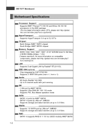
...front x 1) Audio - Chip integrated by Realtek® RTL8111DL IEEE 1394 (optional) - msi.com.tw/index.php?func=cpuform2) HyperTransport - Supports HyperTransport 3.0 up to 3.0 Gb/s RAID - North Bridge: AMD® 790FX chipset - func=testreport) LAN - Supports PIO, Bus Master operation mode SATA - SATA1~6 ...supports RAID 0/ 1/ 10/ 5 or JBOD mode by JMicron® JMB322 - South Bridge: AMD® SB750 chipset Memory Support - Up to 5.2 GT/s Chipset - MS-7577 Mainboard Motherboard ...
...front x 1) Audio - Chip integrated by Realtek® RTL8111DL IEEE 1394 (optional) - msi.com.tw/index.php?func=cpuform2) HyperTransport - Supports HyperTransport 3.0 up to 3.0 Gb/s RAID - North Bridge: AMD® 790FX chipset - func=testreport) LAN - Supports PIO, Bus Master operation mode SATA - SATA1~6 ...supports RAID 0/ 1/ 10/ 5 or JBOD mode by JMicron® JMB322 - South Bridge: AMD® SB750 chipset Memory Support - Up to 5.2 GT/s Chipset - MS-7577 Mainboard Motherboard ...
User Guide
Page 13
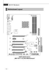
... J SP1 PCI_E4 Audio codec PCI2 PCI_E5 JAUD1 J CD1 (O ptional) J1394_1 Clock Gen. In M:L i ne - JP WR1 MS-7577 Mainboard Motherboard Layout Top : mouse Bottom: keyboard Top: Coaxial S/PDI F Buttom: Optical S/PDI F SY SFAN3 Top: USB JPWM2 Buttom: ES ATA/USB...3 D I /O Chip SATA5-6 JUSB1 JUS B2 OC DRIVE J TPM1 OC GEAR J FP1 JFP2 C L R_ C M OS 1 Gr een Power RESET1 POWER1 790FX-GD70 Series (MS-7577 v1.X) ATX Motherboard 1-4 JMB362 JBAT1 BATT + AMD SB750 JMB322 IDE1 SATA7 SATA8 SATA3-4 S ATA1-2 SYSFAN2 FDD 1 JCI1 POS T_LED J COM1 I MM 4 Top: LAN Jack Bottom...
... J SP1 PCI_E4 Audio codec PCI2 PCI_E5 JAUD1 J CD1 (O ptional) J1394_1 Clock Gen. In M:L i ne - JP WR1 MS-7577 Mainboard Motherboard Layout Top : mouse Bottom: keyboard Top: Coaxial S/PDI F Buttom: Optical S/PDI F SY SFAN3 Top: USB JPWM2 Buttom: ES ATA/USB...3 D I /O Chip SATA5-6 JUSB1 JUS B2 OC DRIVE J TPM1 OC GEAR J FP1 JFP2 C L R_ C M OS 1 Gr een Power RESET1 POWER1 790FX-GD70 Series (MS-7577 v1.X) ATX Motherboard 1-4 JMB362 JBAT1 BATT + AMD SB750 JMB322 IDE1 SATA7 SATA8 SATA3-4 S ATA1-2 SYSFAN2 FDD 1 JCI1 POS T_LED J COM1 I MM 4 Top: LAN Jack Bottom...
User Guide
Page 14
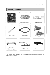
Packing Checklist Getting Started MSI motherboard MSI Driver/Utility CD Back IO Shield Power Cable SATA Cable IDE/ Floppy Cable CrossFire Video Link Cable USB Bracket User's Guide * The pictures are for reference only and may vary from the packing contents of the product you purchased. 1-5
Packing Checklist Getting Started MSI motherboard MSI Driver/Utility CD Back IO Shield Power Cable SATA Cable IDE/ Floppy Cable CrossFire Video Link Cable USB Bracket User's Guide * The pictures are for reference only and may vary from the packing contents of the product you purchased. 1-5
User Guide
Page 17
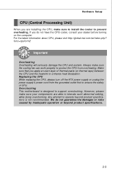
... the damages or risks caused by inadequate operation or beyond product specifications is designed to support overclocking. Overclocking This motherboard is not recommended. For the latest information about CPU, please visit http://global.msi.com.tw/index.php? Any attempt to operate beyond product specifications. 2-3 Hardware Setup CPU (Central Processing Unit) W hen...
... the damages or risks caused by inadequate operation or beyond product specifications is designed to support overclocking. Overclocking This motherboard is not recommended. For the latest information about CPU, please visit http://global.msi.com.tw/index.php? Any attempt to operate beyond product specifications. 2-3 Hardware Setup CPU (Central Processing Unit) W hen...
User Guide
Page 18
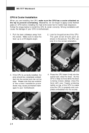
... into the socket. 2-4 W rong installation will cause the damage of the CPU to make sure the CPU has a cooler attached on top of your motherboard. 4. Press the CPU down firmly into the socket and can only fit in the picture. Make sure to raise the lever up to prevent overheating... and close the lever with your f ingers pressing tightly on the top to a 90-degree angle. 2. As the CPU is likely to your CPU & motherboard. 1. Pull the lever sideways away from the socket. Look for better heat dispersion. Follow the steps below to apply some thermal paste on CPU before...
... into the socket. 2-4 W rong installation will cause the damage of the CPU to make sure the CPU has a cooler attached on top of your motherboard. 4. Press the CPU down firmly into the socket and can only fit in the picture. Make sure to raise the lever up to prevent overheating... and close the lever with your f ingers pressing tightly on the top to a 90-degree angle. 2. As the CPU is likely to your CPU & motherboard. 1. Pull the lever sideways away from the socket. Look for better heat dispersion. Follow the steps below to apply some thermal paste on CPU before...
User Guide
Page 19
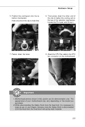
... the Fix Lever and lift up it is disconnected from the fixed bolt, the fixed lever will spring back instantly. 2-5 Motherboard photos shown in this section are for demonstration only. Fasten down the other end of the clip to hook first. 6. The appearance of the retention ...
... the Fix Lever and lift up it is disconnected from the fixed bolt, the fixed lever will spring back instantly. 2-5 Motherboard photos shown in this section are for demonstration only. Fasten down the other end of the clip to hook first. 6. The appearance of the retention ...
User Guide
Page 22
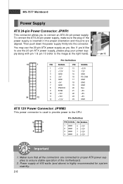
... Important 1. Then push down the power supply firmly into the connector. To connect the ATX 24-pin power supply, make sure the plug of the motherboard. 2. Maker sure that all the connectors are aligned. You may use the 20-pin ATX power supply, please plug your power supply along with pin...
... Important 1. Then push down the power supply firmly into the connector. To connect the ATX 24-pin power supply, make sure the plug of the motherboard. 2. Maker sure that all the connectors are aligned. You may use the 20-pin ATX power supply, please plug your power supply along with pin...
User Guide
Page 27
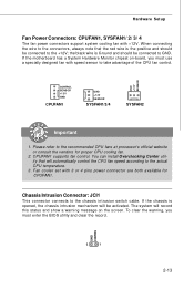
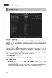
... control. Fan cooler set with +12V. To clear the warning, you must enter the BIOS utility and clear the record. GND CINTRU 2 1 2-13 If the motherboard has a System Hardware Monitor chipset on the screen. CPUFAN1 supports fan control. If the chassis is Ground and should be connected to the actual CPU...
... control. Fan cooler set with +12V. To clear the warning, you must enter the BIOS utility and clear the record. GND CINTRU 2 1 2-13 If the motherboard has a System Hardware Monitor chipset on the screen. CPUFAN1 supports fan control. If the chassis is Ground and should be connected to the actual CPU...
User Guide
Page 33
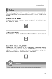
... the button to reset the system. Press the button to turnon or turn-off the system before clearing CMOS data. 2-19 Hardware Setup Button The motherboard provides the following buttons for you want to clear the system configuration, use of button. Important Make sure that has a power supply from external battery..., the system can automatically boot OS every time it is used to keep the system configuration data. This section will explain how to change your motherboard's function through the use the button to reset the system.
... the button to reset the system. Press the button to turnon or turn-off the system before clearing CMOS data. 2-19 Hardware Setup Button The motherboard provides the following buttons for you want to clear the system configuration, use of button. Important Make sure that has a power supply from external battery..., the system can automatically boot OS every time it is used to keep the system configuration data. This section will explain how to change your motherboard's function through the use the button to reset the system.
User Guide
Page 37
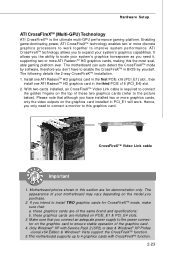
... Pack 2 (SP2) or later & Windows® XP Profes -sional x64 Edition & Windows® Vista support the CrossFireXTM function. 5.This motherboard supports up to expand your system's graphics horsepower as you need to connect a monitor to the power connector on the model you connect an .... b. Enabling game-dominating power, ATI CrossFireXTM technology enables two or more ATI RadeonTM HD graphics cards, making this graphics card. The motherboard can auto detect the CrossFireXTM mode by yourself. W ith two cards installed, an CrossFireXTM Video Link cable is the ultimate multi-GPU...
... Pack 2 (SP2) or later & Windows® XP Profes -sional x64 Edition & Windows® Vista support the CrossFireXTM function. 5.This motherboard supports up to expand your system's graphics horsepower as you need to connect a monitor to the power connector on the model you connect an .... b. Enabling game-dominating power, ATI CrossFireXTM technology enables two or more ATI RadeonTM HD graphics cards, making this graphics card. The motherboard can auto detect the CrossFireXTM mode by yourself. W ith two cards installed, an CrossFireXTM Video Link cable is the ultimate multi-GPU...
User Guide
Page 46
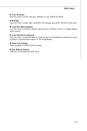
Save & Exit Setup Save changes to load the default values set by the motherboard manufacturer specifically for optimal performance of the motherboard. Load Optimized Defaults Use this menu to CMOS and exit setup. M-Flash Use this menu to load the default values set by the BIOS vendor for BIOS. Load Fail-Safe Defaults Use this menu to read/ flash the BIOS from CMOS for stable system performance. BIOS Setup User Settings Use this menu to save/ load your settings to/ from storage drive (FAT/ FAT32 format only). Exit Without Saving Abandon all changes and exit setup. 3-5
Save & Exit Setup Save changes to load the default values set by the motherboard manufacturer specifically for optimal performance of the motherboard. Load Optimized Defaults Use this menu to CMOS and exit setup. M-Flash Use this menu to load the default values set by the BIOS vendor for BIOS. Load Fail-Safe Defaults Use this menu to read/ flash the BIOS from CMOS for stable system performance. BIOS Setup User Settings Use this menu to save/ load your settings to/ from storage drive (FAT/ FAT32 format only). Exit Without Saving Abandon all changes and exit setup. 3-5
User Guide
Page 48
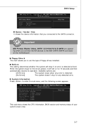
... the errors preset, it will stop for 15 seconds and then automatically resume its operation. System Information Press to the SATA connector. Hold on the motherboard. The system doesn't stop if an error is detected. BIOS Setup Device / Vender / Size It shows the device information that you connected to enter the...
... the errors preset, it will stop for 15 seconds and then automatically resume its operation. System Information Press to the SATA connector. Hold on the motherboard. The system doesn't stop if an error is detected. BIOS Setup Device / Vender / Size It shows the device information that you connected to enter the...
User Guide
Page 57
SYS FAN 1/ 2/ 3/ 4 Control This item allows users to keep it with in a specific range. CPU Smart FAN Target The motherboard provides the Smart Fan function which can select a fan target value here. PC Health Status CPU/ System Temperature, CPU FAN/ SYS FAN 1/ 2/ 3/ 4 Speed, CPU Vcore, 3....
SYS FAN 1/ 2/ 3/ 4 Control This item allows users to keep it with in a specific range. CPU Smart FAN Target The motherboard provides the Smart Fan function which can select a fan target value here. PC Health Status CPU/ System Temperature, CPU FAN/ SYS FAN 1/ 2/ 3/ 4 Speed, CPU Vcore, 3....
User Guide
Page 58
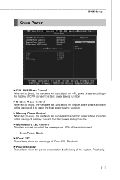
... power consumption & efficiency of the system. Read only. Pout/ Efficiency These items show the amperage of Core/ 12V. Motherboard LED Control This item is used to control the power phase LEDs of the motherboard. ----- Read only. 3-17 System Phase Control W hen set to [Auto], the hardware will auto adjust the CPU power...
... power consumption & efficiency of the system. Read only. Pout/ Efficiency These items show the amperage of Core/ 12V. Motherboard LED Control This item is used to control the power phase LEDs of the motherboard. ----- Read only. 3-17 System Phase Control W hen set to [Auto], the hardware will auto adjust the CPU power...
User Guide
Page 65
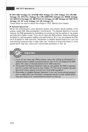
.... 3. Remember to disable Spread Spectrum if you do not have any EMI problem, leave the setting at [Disabled] for EMI reduction. 2. Spread Spectrum W hen the motherboard's clock generator pulses, the extreme values (spikes) of CPU, Memory and chipset. The greater the Spread Spectrum value is, the greater the EMI is reduced...
.... 3. Remember to disable Spread Spectrum if you do not have any EMI problem, leave the setting at [Disabled] for EMI reduction. 2. Spread Spectrum W hen the motherboard's clock generator pulses, the extreme values (spikes) of CPU, Memory and chipset. The greater the Spread Spectrum value is, the greater the EMI is reduced...
User Guide
Page 66
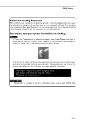
... reboot actions. 2. However, please make sure your system from improper operation will not be under our product warranty. W arning !!! BIOS Setup Failed Overclocking Resolution This motherboard supports overclocking greatly. Any operation that the previous overclocking is not recommended. Two ways to "chapter 2" for some special settings. The previous overclocking had failed...
... reboot actions. 2. However, please make sure your system from improper operation will not be under our product warranty. W arning !!! BIOS Setup Failed Overclocking Resolution This motherboard supports overclocking greatly. Any operation that the previous overclocking is not recommended. Two ways to "chapter 2" for some special settings. The previous overclocking had failed...
User Guide
Page 71
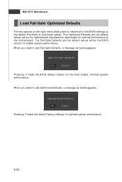
... system performance. 3-30 MS-7577 Mainboard Load Fail-Safe/ Optimized Defaults The two options on the main menu allow users to restore all of the motherboard. The Fail-Safe Defaults are the default values set by the...
... system performance. 3-30 MS-7577 Mainboard Load Fail-Safe/ Optimized Defaults The two options on the main menu allow users to restore all of the motherboard. The Fail-Safe Defaults are the default values set by the...
User Guide
Page 93
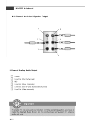
a A-22 MS-7577 Mainboard n 8-Channel Mode for 8-Speaker Output 1 4 2 5 3 6 8-Channel Analog Audio Output 1 Line In 2 Line Out (Front channels) 3 MIC 4 Line Out (Rear channels) 5 Line Out (Center and Subwoofer channel) 6 Line Out (Side channels) Important To enable 7.1 channel audio-out function on Vista operating system, you have to install the Realtek Audio Driver. Or, the motherboard will support 5.1 channel audio-out only.
a A-22 MS-7577 Mainboard n 8-Channel Mode for 8-Speaker Output 1 4 2 5 3 6 8-Channel Analog Audio Output 1 Line In 2 Line Out (Front channels) 3 MIC 4 Line Out (Rear channels) 5 Line Out (Center and Subwoofer channel) 6 Line Out (Side channels) Important To enable 7.1 channel audio-out function on Vista operating system, you have to install the Realtek Audio Driver. Or, the motherboard will support 5.1 channel audio-out only.
User Guide
Page 94
Operation system: W indows XP or up. 4. DotNet Frame Work 2.0 B-1 DVD-ROM drive for software installation. 3. Overclocking Center Appendix B Overclocking Center Overclocking Center, the most useful and powerful utility that MSI has spent much research and efforts to develop, helps users to monitor or configure the hardware status of MSI Motherboard in windows, such as CPU clock, voltage, fan speed and temperature. Before you install the Overclocking Center, please make sure the system has meet the following requirements: 1. 256MB system memory. 2.
Operation system: W indows XP or up. 4. DotNet Frame Work 2.0 B-1 DVD-ROM drive for software installation. 3. Overclocking Center Appendix B Overclocking Center Overclocking Center, the most useful and powerful utility that MSI has spent much research and efforts to develop, helps users to monitor or configure the hardware status of MSI Motherboard in windows, such as CPU clock, voltage, fan speed and temperature. Before you install the Overclocking Center, please make sure the system has meet the following requirements: 1. 256MB system memory. 2.


