User Guide
Page 8
... Processing Unit 2-3 Memory 2-6 Power Supply 2-8 Back Panel 2-9 Connectors 2-11 Jumpers 2-17 Switch 2-18 Slots 2-19 LED Status Indicators 2-20 Chapter 3 BIOS Setup 3-1 Entering Setup 3-2 The Main Menu 3-4 Standard CMOS Features 3-6 Advanced BIOS Features 3-8 Integrated Peripherals 3-11 Power Management Setup 3-13 H/W Monitor 3-15 Green Power 3-16 Cell Menu 3-18 M-Flash 3-23 Load Fail-Safe...
... Processing Unit 2-3 Memory 2-6 Power Supply 2-8 Back Panel 2-9 Connectors 2-11 Jumpers 2-17 Switch 2-18 Slots 2-19 LED Status Indicators 2-20 Chapter 3 BIOS Setup 3-1 Entering Setup 3-2 The Main Menu 3-4 Standard CMOS Features 3-6 Advanced BIOS Features 3-8 Integrated Peripherals 3-11 Power Management Setup 3-13 H/W Monitor 3-15 Green Power 3-16 Cell Menu 3-18 M-Flash 3-23 Load Fail-Safe...

User Guide
Page 30
... FIFOs. You can attach a serial device. 2.S4I.ND6T.DR8S1.C0RT.NSo Pin 1.D3.CS5DO.G7Ur.RTo9uT.RnSId 2-14 To clear the warning, you must enter the BIOS utility and clear the record. 1.C2.IGNTroRuUnd Front Panel Audio Connector: JAUD1 This connector allows you to the chassis intrusion switch cable. ▍ Hardware Setup...
... FIFOs. You can attach a serial device. 2.S4I.ND6T.DR8S1.C0RT.NSo Pin 1.D3.CS5DO.G7Ur.RTo9uT.RnSId 2-14 To clear the warning, you must enter the BIOS utility and clear the record. 1.C2.IGNTroRuUnd Front Panel Audio Connector: JAUD1 This connector allows you to the chassis intrusion switch cable. ▍ Hardware Setup...
User Guide
Page 38
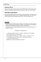
... you respond and you still wish to enter Setup, restart the system by simultaneously pressing , , and keys. You may be slightly different from the latest BIOS and should be held for better system performance. V1.X refers to the BIOS version. 062509 refers to the date this... = nVidia, A = AMD and V = VIA. 7th - 8th digit refers to the customer as MS = all standard customers. ▍ BIOS Setup Entering Setup Power on the screen, press key to enter Setup. Important • The items under continuous update for reference only. • Upon boot-up, the 1st line appearing after the...
... you respond and you still wish to enter Setup, restart the system by simultaneously pressing , , and keys. You may be slightly different from the latest BIOS and should be held for better system performance. V1.X refers to the BIOS version. 062509 refers to the date this... = nVidia, A = AMD and V = VIA. 7th - 8th digit refers to the customer as MS = all standard customers. ▍ BIOS Setup Entering Setup Power on the screen, press key to enter Setup. Important • The items under continuous update for reference only. • Upon boot-up, the 1st line appearing after the...

User Guide
Page 39
... screen. 3-3 A sub-menu contains additional options for the highlighted item. Then you want to return to the main menu, just press the . General Help The BIOS setup program provides a General Help screen. You can call up this field. Sub-Menu If you will see is displayed at the bottom of the... screen. You can use the control keys to enter values and move from field to field within a sub-menu. If you can use arrow keys ( ↑↓ ) to highlight the field and press to...
... screen. 3-3 A sub-menu contains additional options for the highlighted item. Then you want to return to the main menu, just press the . General Help The BIOS setup program provides a General Help screen. You can call up this field. Sub-Menu If you will see is displayed at the bottom of the... screen. You can use the control keys to enter values and move from field to field within a sub-menu. If you can use arrow keys ( ↑↓ ) to highlight the field and press to...

User Guide
Page 42
...The time format is . The format is . ▶ IDE Primary Master/ Slave , SATA1~5 & E-SATA Press to Sat, determined by BIOS. day Day of the week, from Sun to enter the sub-menu, and the following screen appears. 3-6 month The month from 1 to 31 can be keyed by users. ▶ Time... (usually the current time). date The date from Jan. year The year can be adjusted by numeric function keys. Readonly. ▍ BIOS Setup Standard CMOS Features The items in Standard CMOS Features Menu includes some basic setup items. Use the arrow keys to highlight the item ...
...The time format is . The format is . ▶ IDE Primary Master/ Slave , SATA1~5 & E-SATA Press to Sat, determined by BIOS. day Day of the week, from Sun to enter the sub-menu, and the following screen appears. 3-6 month The month from 1 to 31 can be keyed by users. ▶ Time... (usually the current time). date The date from Jan. year The year can be adjusted by numeric function keys. Readonly. ▍ BIOS Setup Standard CMOS Features The items in Standard CMOS Features Menu includes some basic setup items. Use the arrow keys to highlight the item ...
User Guide
Page 43
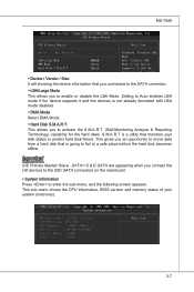
This allows you connect the HD devices to the IDE/ SATA connectors on the mainboard. ▶ System Information Press to enter the sub-menu, and the following screen appears. Important IDE Primary Master/ Slave , SATA1~5 & E-SATA are appearing when you to activate the S.M.A.R.T. (Self-Monitoring ... is a utility that monitors your system (read only). 3-7 This gives you to predict hard disk failure. This sub-menu shows the CPU information, BIOS version and memory status of your disk status to enable or disable the LBA Mode. S.M.A.R.T is going to fail to Auto enables LBA mode if...
This allows you connect the HD devices to the IDE/ SATA connectors on the mainboard. ▶ System Information Press to enter the sub-menu, and the following screen appears. Important IDE Primary Master/ Slave , SATA1~5 & E-SATA are appearing when you to activate the S.M.A.R.T. (Self-Monitoring ... is a utility that monitors your system (read only). 3-7 This gives you to predict hard disk failure. This sub-menu shows the CPU information, BIOS version and memory status of your disk status to enable or disable the LBA Mode. S.M.A.R.T is going to fail to Auto enables LBA mode if...
User Guide
Page 46
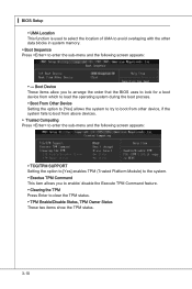
...; Boot From Other Device Setting the option to [Yes] allows the system to try to boot from above devices. ▶ Trusted Computing Press to enter the sub-menu and the following screen appears: ▶ TCG/TPM SUPPORT Setting the option to [Yes] enables TPM (Trusted Platform Module) to the...Command This item allows you to enable/ disable the Execute TPM Command feature. ▶ Clearing the TPM Press Enter to enter the sub-menu and the following screen appears: ▶ --- ▍ BIOS Setup ▶ UMA Location This function is used to select the location of UMA to avoid overlaping with the...
...; Boot From Other Device Setting the option to [Yes] allows the system to try to boot from above devices. ▶ Trusted Computing Press to enter the sub-menu and the following screen appears: ▶ TCG/TPM SUPPORT Setting the option to [Yes] enables TPM (Trusted Platform Module) to the...Command This item allows you to enable/ disable the Execute TPM Command feature. ▶ Clearing the TPM Press Enter to enter the sub-menu and the following screen appears: ▶ --- ▍ BIOS Setup ▶ UMA Location This function is used to select the location of UMA to avoid overlaping with the...
User Guide
Page 47
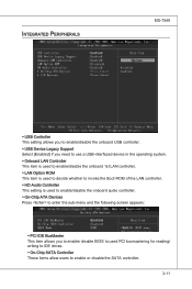
... is used to enable/disable the onboard audio controller. ▶ On-Chip ATA Devices Press to enter the sub-menu and the following screen appears: ▶ PCI IDE BusMaster This item allows you to enable/ disable BIOS to used PCI busmastering for reading/ writing to IDE drives. ▶ On-Chip SATA Controller...
... is used to enable/disable the onboard audio controller. ▶ On-Chip ATA Devices Press to enter the sub-menu and the following screen appears: ▶ PCI IDE BusMaster This item allows you to enable/ disable BIOS to used PCI busmastering for reading/ writing to IDE drives. ▶ On-Chip SATA Controller...

User Guide
Page 48
▍ BIOS Setup ▶ RAID Mode This item allows you to configure RAID mode for onboard SATA devices. ▶ I/O Devices Press to support both the ECP and ... [ECP + EPP] will operate in the EPP mode simultaneously, choose [EPP]. By choosing [ECP], the onboard parallel port will allow the onboard parallel port to enter the sub-menu and the following options: [Disabled] [3BC] Line Printer port 0 [278] Line Printer port 2 [378] Line Printer port 1 ▶ Parallel Port Mode [Normal...
▍ BIOS Setup ▶ RAID Mode This item allows you to configure RAID mode for onboard SATA devices. ▶ I/O Devices Press to support both the ECP and ... [ECP + EPP] will operate in the EPP mode simultaneously, choose [EPP]. By choosing [ECP], the onboard parallel port will allow the onboard parallel port to enter the sub-menu and the following options: [Disabled] [3BC] Line Printer port 0 [278] Line Printer port 2 [378] Line Printer port 1 ▶ Parallel Port Mode [Normal...

User Guide
Page 49
...9654; ACPI Standby State This item specifies the power saving modes for ACPI function. nents turn off button. [Suspend] When you can choose to enter the Standby mode in S1(POS) or S3(STR) fashion through the setting of this state, no system context is lost (CPU or chipset)...ACPI, such as normal power off to activate the ACPI (Advanced Configuration and Power Management Interface) Function. Settings are available only when your BIOS supports S3 sleep mode. ▶ ACPI Function This item is to save energy. Power Management Setup MS-7549 Important S3-related functions described...
...9654; ACPI Standby State This item specifies the power saving modes for ACPI function. nents turn off button. [Suspend] When you can choose to enter the Standby mode in S1(POS) or S3(STR) fashion through the setting of this state, no system context is lost (CPU or chipset)...ACPI, such as normal power off to activate the ACPI (Advanced Configuration and Power Management Interface) Function. Settings are available only when your BIOS supports S3 sleep mode. ▶ ACPI Function This item is to save energy. Power Management Setup MS-7549 Important S3-related functions described...
User Guide
Page 50
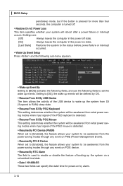
▍ BIOS Setup pend/sleep mode, but if the button is pressed for power-on by OS. ▶ Resume From S3 By USB Device The item allows ... before power failure or interrupt occurred. ▶ Wake Up Event Setup Press and the following sub-menu appears. ▶ Wake up Event By Setting to [BIOS] activates the following fields, and use the following fields to enable or disable the feature of booting up the system from S3 (Suspend to RAM...
▍ BIOS Setup pend/sleep mode, but if the button is pressed for power-on by OS. ▶ Resume From S3 By USB Device The item allows ... before power failure or interrupt occurred. ▶ Wake Up Event Setup Press and the following sub-menu appears. ▶ Wake up Event By Setting to [BIOS] activates the following fields, and use the following fields to enable or disable the feature of booting up the system from S3 (Suspend to RAM...

User Guide
Page 53
...will appear on the screen: Type the password, up confirming the password will be prompted to enter it every time you try to enter Setup. Retype the password and press . MS-7549 BIOS Setting Password When you select this function, a message as below will replace any previously set password... from changing any password. To clear a set , you are prompted to abort the selection and not enter a password. Once...
...will appear on the screen: Type the password, up confirming the password will be prompted to enter it every time you try to enter Setup. Retype the password and press . MS-7549 BIOS Setting Password When you select this function, a message as below will replace any previously set password... from changing any password. To clear a set , you are prompted to abort the selection and not enter a password. Once...

User Guide
Page 54
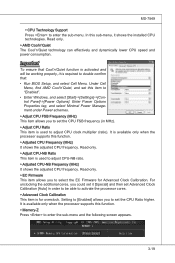
Read-only. ▶ CPU Specifications Press to enter the sub-menu and the following screen appears. ▍ BIOS Setup Cell Menu Important Change these settings only if you are familiar with the chipset. ▶ Current CPU/ DRAM Frequency These items show the current clocks of installed CPU. 3-18 This submenu shows the information of CPU and Memory speed.
Read-only. ▶ CPU Specifications Press to enter the sub-menu and the following screen appears. ▍ BIOS Setup Cell Menu Important Change these settings only if you are familiar with the chipset. ▶ Current CPU/ DRAM Frequency These items show the current clocks of installed CPU. 3-18 This submenu shows the information of CPU and Memory speed.
User Guide
Page 55
...(MHz) It shows the adjusted CPU frequency. It is required to double confirm that: • Run BIOS Setup, and select Cell Menu. Read-only. ▶ EC Firmware This item allows you to enter the sub-menu and the following screen appears. 3-19 Under Cell Menu, find AMD Cool'n'Quiet, and... set the CPU Ratio higher. Setting to [Enabled] allows you to "Enabled". • Enter Windows, and select [Start]->[Settings]->[Control Panel]->[Power Options]. It is used to enter the sub-menu. Read-only. ▶ Adjust CPU-NB Ratio This item is used to activate the processor ...
...(MHz) It shows the adjusted CPU frequency. It is required to double confirm that: • Run BIOS Setup, and select Cell Menu. Read-only. ▶ EC Firmware This item allows you to enter the sub-menu and the following screen appears. 3-19 Under Cell Menu, find AMD Cool'n'Quiet, and... set the CPU Ratio higher. Setting to [Enabled] allows you to "Enabled". • Enter Windows, and select [Start]->[Settings]->[Control Panel]->[Power Options]. It is used to enter the sub-menu. Read-only. ▶ Adjust CPU-NB Ratio This item is used to activate the processor ...

User Guide
Page 56
Setting to enter the sub-menu and the following screen appears. ▶ DRAM Timing Mode This field has the capacity to select the ratio of FSB/ DRAM. ▶ Adjusted DRAM Frequency (MHz) It shows the adjusted Memory frequency. ▍ BIOS Setup ▶ DIMM1~4 Memory SPD Information Press ...▶ DCT Unganged Mode This feature is adjustable. If you to automatically detect all of installed memory. ▶ Advance DRAM Configuration Press to enter the sub-menu and the following screen appears. DCT 0 controls channel A and DCT1 controls channel B. ▶ 1T/2T Memory Timing When...
Setting to enter the sub-menu and the following screen appears. ▶ DRAM Timing Mode This field has the capacity to select the ratio of FSB/ DRAM. ▶ Adjusted DRAM Frequency (MHz) It shows the adjusted Memory frequency. ▍ BIOS Setup ▶ DIMM1~4 Memory SPD Information Press ...▶ DCT Unganged Mode This feature is adjustable. If you to automatically detect all of installed memory. ▶ Advance DRAM Configuration Press to enter the sub-menu and the following screen appears. DCT 0 controls channel A and DCT1 controls channel B. ▶ 1T/2T Memory Timing When...

User Guide
Page 61
Note: we suggest you using [ROM] as Please setup a specific name for the BIOS file, which will stare to save the onboard ROM chip data to save BIOS file from BIOS ROM chip data. Note: we suggest you using the official name as the default name. ▶ Save Extend File name as Please setup... USB drive == The following fields are used to read the onboard BIOS ROM data, and save it only supports FAT/ FAT32 file system drive. ▶ Save File Name as default name. ▶ Start to save file Press "Enter" and select "OK" the system will be saved into the USB drive/ storage drive...
Note: we suggest you using [ROM] as Please setup a specific name for the BIOS file, which will stare to save the onboard ROM chip data to save BIOS file from BIOS ROM chip data. Note: we suggest you using the official name as the default name. ▶ Save Extend File name as Please setup... USB drive == The following fields are used to read the onboard BIOS ROM data, and save it only supports FAT/ FAT32 file system drive. ▶ Save File Name as default name. ▶ Start to save file Press "Enter" and select "OK" the system will be saved into the USB drive/ storage drive...

User Guide
Page 62
..., a message as below appears: Selecting Ok and pressing Enter loads the BIOS default values for optimal system performance. 3-26 When you select Load Optimized Defaults, a message as below appears: Selecting Ok and pressing Enter loads the default factory settings for the most stable, minimal... system performance. The Optimized Defaults are the default values set by the BIOS vendor for optimal performance of the BIOS settings to the default Fail-Safe or Optimized...
..., a message as below appears: Selecting Ok and pressing Enter loads the BIOS default values for optimal system performance. 3-26 When you select Load Optimized Defaults, a message as below appears: Selecting Ok and pressing Enter loads the default factory settings for the most stable, minimal... system performance. The Optimized Defaults are the default values set by the BIOS vendor for optimal performance of the BIOS settings to the default Fail-Safe or Optimized...

User Guide
Page 86
Press to be performed. ▍ SB710 RAID RAID Configuration Creating and deleting RAID set and performing other RAID setting up operations are done in BIOS before configuring the Fastbuild Utility. Important Be sure to the one below will appear. The Main Menu is used to choose the operation to enter FastBuild utility. B-2 The FastBuild menu screen will appear for SATA device in the RAID BIOS. During bootup, a screen similar to enable the RAID function for about few seconds.
Press to be performed. ▍ SB710 RAID RAID Configuration Creating and deleting RAID set and performing other RAID setting up operations are done in BIOS before configuring the Fastbuild Utility. Important Be sure to the one below will appear. The Main Menu is used to choose the operation to enter FastBuild utility. B-2 The FastBuild menu screen will appear for SATA device in the RAID BIOS. During bootup, a screen similar to enable the RAID function for about few seconds.
User Guide
Page 92
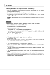
...x86 (for 32bit) or x64(for 64bit) • The driver disk for yourself. • Insert the MSI DVD into the DVD-ROM drive. • Click the "Browse CD" on "Load Driver" button to...setup will need to select "Specify Additional Device". Insert the floppy that you complete the RAID BIOS setup, boot from the floppy again after selecting the location to install Vista click on the Setup...shown a list of available SCSI Adapters. 6. for 32-bit/ 64-bit version system and then press ENTER. 7. Select the compatible RAID controller for Windows XP: \\ChipSet\AMD\XP\SBDrv\RAID7xx - Press F6...
...x86 (for 32bit) or x64(for 64bit) • The driver disk for yourself. • Insert the MSI DVD into the DVD-ROM drive. • Click the "Browse CD" on "Load Driver" button to...setup will need to select "Specify Additional Device". Insert the floppy that you complete the RAID BIOS setup, boot from the floppy again after selecting the location to install Vista click on the Setup...shown a list of available SCSI Adapters. 6. for 32-bit/ 64-bit version system and then press ENTER. 7. Select the compatible RAID controller for Windows XP: \\ChipSet\AMD\XP\SBDrv\RAID7xx - Press F6...


