User Guide
Page 3
ing. ■ Place the power cord such a way that can cause damage or cause elec- Visit the MSI website for technical guide, BIOS updates, driver updates, and other information: http://www.msi.com/service/download/ Contact our technical staff at 110/220V before connect- trical shock. ■ If any of purchase or local distributor. Technical Support If a problem arises with your place of the...
ing. ■ Place the power cord such a way that can cause damage or cause elec- Visit the MSI website for technical guide, BIOS updates, driver updates, and other information: http://www.msi.com/service/download/ Contact our technical staff at 110/220V before connect- trical shock. ■ If any of purchase or local distributor. Technical Support If a problem arises with your place of the...
User Guide
Page 4
... be used in a residential installation. Increase the separation between the equipment and receiver. Notice 2 Shielded interface cables and A.C. Notice 1 The changes or modifications not expressly approved by one or more of the FCC Rules. Micro-Star International MS-7641 This device complies with the instruction manual, may not cause harmful interference, and (2) this device must be determined by turning the...
... be used in a residential installation. Increase the separation between the equipment and receiver. Notice 2 Shielded interface cables and A.C. Notice 1 The changes or modifications not expressly approved by one or more of the FCC Rules. Micro-Star International MS-7641 This device complies with the instruction manual, may not cause harmful interference, and (2) this device must be determined by turning the...
User Guide
Page 7
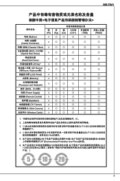
...+) PBB) 电池 (Battery) ☓ 〇 〇 〇 〇 Cable/ Connector) ☓ 〇 〇 〇 〇 Chassis/ Other) ☓ 〇 〇 〇 〇 CD, DVD等) (Optical Disk Driver) ☓ 〇 〇 〇 〇 Hard Disk Driver) ☓ 〇 〇 〇 〇 PCAs)* ☓ 〇 〇 〇 〇 I/O Device) (如Mouse, Keyboard等) ☓ 〇 〇 〇 〇 LCD Panel) ☓ ☓ 〇...
...+) PBB) 电池 (Battery) ☓ 〇 〇 〇 〇 Cable/ Connector) ☓ 〇 〇 〇 〇 Chassis/ Other) ☓ 〇 〇 〇 〇 CD, DVD等) (Optical Disk Driver) ☓ 〇 〇 〇 〇 Hard Disk Driver) ☓ 〇 〇 〇 〇 PCAs)* ☓ 〇 〇 〇 〇 I/O Device) (如Mouse, Keyboard等) ☓ 〇 〇 〇 〇 LCD Panel) ☓ ☓ 〇...
User Guide
Page 13
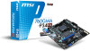
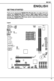
... AMD® 760G & SB710 chipset for choosing the 760GMA-P34 (FX) (MS-7641 v5.x) Micro-ATX motherboard. MS-7641 English Getting startED Thank you for optimal system efficiency. Designed to fit the advanced AMD® processor in AM3+ package, the 760GMA-P34 (FX) Series deliver a high performance and professional desktop ... JUSB_PW2 JUSB3 JUSB1 JUSB2 JFP2 JFP1 JBAT1 SATA2 SATA4 SATA6 SATA8 13 Layout Top : mouse JPWR2 Bottom:keyboard CPUFAN JCI1 Top: VGA Port Bottom: DVI JUSB_PW1 JPWR1 SYSFAN2 USB2.0 ports USB3.0 ports Top: LAN Jack Bottom: USB2.0 ports T:Line-In M:Line-
... AMD® 760G & SB710 chipset for choosing the 760GMA-P34 (FX) (MS-7641 v5.x) Micro-ATX motherboard. MS-7641 English Getting startED Thank you for optimal system efficiency. Designed to fit the advanced AMD® processor in AM3+ package, the 760GMA-P34 (FX) Series deliver a high performance and professional desktop ... JUSB_PW2 JUSB3 JUSB1 JUSB2 JFP2 JFP1 JBAT1 SATA2 SATA4 SATA6 SATA8 13 Layout Top : mouse JPWR2 Bottom:keyboard CPUFAN JCI1 Top: VGA Port Bottom: DVI JUSB_PW1 JPWR1 SYSFAN2 USB2.0 ports USB3.0 ports Top: LAN Jack Bottom: USB2.0 ports T:Line-In M:Line-
User Guide
Page 14
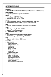
... 1061 ■ 6 SATA 3Gb/s ports (SATA1~6) by AMD® SB710 RAID ■ Supports RAID 0/ 1/ 10 or JBOD mode Connectors ■ Back Panel I/O ‑ 1 PS/2 mouse port ‑ 1 PS/2 keyboard port ‑ 1 VGA port ‑ 1 DVI-D port ‑ 4 USB 2.0 ports ‑ 2 USB 3.0 ports ‑ 1 LAN jack ‑ 3 flexible audio jacks ■ Onboard Connectors ‑ 1 USB 3.0 connector ‑ 2 USB 2.0 connectors ‑ 1 Front Audio connector ‑ 1 Serial Port connecotr ‑ 1 TPM connector ‑ 1 Chassis Instrusion Connector 14 SPECIFICATIONS Processor ■ AMD® FX...
... 1061 ■ 6 SATA 3Gb/s ports (SATA1~6) by AMD® SB710 RAID ■ Supports RAID 0/ 1/ 10 or JBOD mode Connectors ■ Back Panel I/O ‑ 1 PS/2 mouse port ‑ 1 PS/2 keyboard port ‑ 1 VGA port ‑ 1 DVI-D port ‑ 4 USB 2.0 ports ‑ 2 USB 3.0 ports ‑ 1 LAN jack ‑ 3 flexible audio jacks ■ Onboard Connectors ‑ 1 USB 3.0 connector ‑ 2 USB 2.0 connectors ‑ 1 Front Audio connector ‑ 1 Serial Port connecotr ‑ 1 TPM connector ‑ 1 Chassis Instrusion Connector 14 SPECIFICATIONS Processor ■ AMD® FX...
User Guide
Page 20
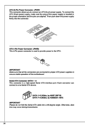
...#.ruR1do2n.eu+2ds2n5.+3dV2.5+4V5.GVround ATX 4-Pin Power Connector: JPWR2 This 4-Pin power connector is used to provide power to ensure stable operation of the power supply is a high-speed Serial ATA interface port. Each connector can connect to connect an ATX 24-pin power supply. Then push down the power supply firmly into a 90-degree angle. To connect the ATX 24-pin power supply, make sure the plug of the motherboard. ATX 24-Pin Power Connector: JPWR1 This connector allows you to one Serial ATA device.
...#.ruR1do2n.eu+2ds2n5.+3dV2.5+4V5.GVround ATX 4-Pin Power Connector: JPWR2 This 4-Pin power connector is used to provide power to ensure stable operation of the power supply is a high-speed Serial ATA interface port. Each connector can connect to connect an ATX 24-pin power supply. Then push down the power supply firmly into a 90-degree angle. To connect the ATX 24-pin power supply, make sure the plug of the motherboard. ATX 24-Pin Power Connector: JPWR1 This connector allows you to one Serial ATA device.
User Guide
Page 21
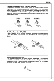
... The fan power connectors support system cooling fan with Intel® Front Panel I/O Connectivity Design Guide. If the chassis is Ground and should be activated. The system will be connected to take advantage of the CPU fan control. the black wire is opened, the chassis intrusion mechanism will record this status and show a warning message on the screen. To clear the warning, you must enter the BIOS utility and clear the...
... The fan power connectors support system cooling fan with Intel® Front Panel I/O Connectivity Design Guide. If the chassis is Ground and should be activated. The system will be connected to take advantage of the CPU fan control. the black wire is opened, the chassis intrusion mechanism will record this status and show a warning message on the screen. To clear the warning, you must enter the BIOS utility and clear the...
User Guide
Page 23
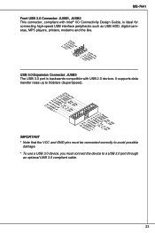
... USB 2.0 Connector: JUSB1, JUSB2 This connector, compliant with Intel® I/O Connectivity Design Guide, is ideal for connecting high-speed USB interface peripherals such as USB HDD, digital cameras, MP3 players, printers, modems and the like. 2.V4C.U6C.SU8BS1.1G0B-r.1No+uCnd 1.V3C.U5CS.U7BS.0G9B-.rN0o+ounPdin USB 3.0 Expansion Connector: JUSB3 The USB 3.0 port is backwards compatible with USB 2.0 devices. It supports data transfer rates up to a USB 3.0 port through an optional USB...
... USB 2.0 Connector: JUSB1, JUSB2 This connector, compliant with Intel® I/O Connectivity Design Guide, is ideal for connecting high-speed USB interface peripherals such as USB HDD, digital cameras, MP3 players, printers, modems and the like. 2.V4C.U6C.SU8BS1.1G0B-r.1No+uCnd 1.V3C.U5CS.U7BS.0G9B-.rN0o+ounPdin USB 3.0 Expansion Connector: JUSB3 The USB 3.0 port is backwards compatible with USB 2.0 devices. It supports data transfer rates up to a USB 3.0 port through an optional USB...
User Guide
Page 24
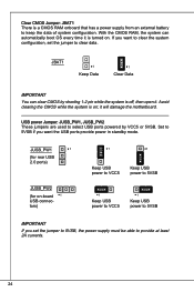
... shorting 1-2 pin while the system is off, then open it will damage the motherboard. JBAT1 1 Keep Data 1 Clear Data Important You can automatically boot OS every time it is turned on ; Clear CMOS Jumper: JBAT1 There is a CMOS RAM onboard that has a power supply from an external battery to clear data. If you set the jumper to keep the data of system configuration. JUSB_PW1 1 (for rear USB 2.0 ports) JUSB_PW2 (for on-board 1 USB connectors...
... shorting 1-2 pin while the system is off, then open it will damage the motherboard. JBAT1 1 Keep Data 1 Clear Data Important You can automatically boot OS every time it is turned on ; Clear CMOS Jumper: JBAT1 There is a CMOS RAM onboard that has a power supply from an external battery to clear data. If you set the jumper to keep the data of system configuration. JUSB_PW1 1 (for rear USB 2.0 ports) JUSB_PW2 (for on-board 1 USB connectors...
User Guide
Page 25
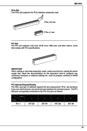
... Slot PCI 1 1 INT E# 2 INT F# 3 INT G# 4 INT H# 25 The PCI IRQ pins are hardware lines over which devices can send interrupt signals to the microprocessor. PCIe x16 slot. PCI Interrupt Request Routing The IRQ, acronym of interrupt request line and pronounced I-R-Q, are typically connected to configure any necessary hardware or software settings for the expansion card to the PCI bus pins as jumpers, switches or BIOS configuration. PCIe Slot The PCIe slot supports the PCIe interface expansion card...
... Slot PCI 1 1 INT E# 2 INT F# 3 INT G# 4 INT H# 25 The PCI IRQ pins are hardware lines over which devices can send interrupt signals to the microprocessor. PCIe x16 slot. PCI Interrupt Request Routing The IRQ, acronym of interrupt request line and pronounced I-R-Q, are typically connected to configure any necessary hardware or software settings for the expansion card to the PCI bus pins as jumpers, switches or BIOS configuration. PCIe Slot The PCIe slot supports the PCIe interface expansion card...
User Guide
Page 26
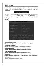
... configurations, such as time, date etc. You may also restart the system by turning it OFF and On or pressing the RESET button. BIOS Setup Power on the screen, press key to specify the power phase. 26 Integrated Peripherals Use this menu to enter Setup. When the message below appears on the computer and the system will start POST (Power On Self Test) process. Green Power Use this menu to enter Setup...
... configurations, such as time, date etc. You may also restart the system by turning it OFF and On or pressing the RESET button. BIOS Setup Power on the screen, press key to specify the power phase. 26 Integrated Peripherals Use this menu to enter Setup. When the message below appears on the computer and the system will start POST (Power On Self Test) process. Green Power Use this menu to enter Setup...
User Guide
Page 27
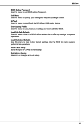
Overclocking Profile Use this menu to save/ load your settings for BIOS. Save & Exit Setup Save changes to / from USB media device. Load Optimized Defaults Use this menu to read/ flash the BIOS from CMOS for frequency/voltage control. M-Flash Use this menu to load factory default settings into the BIOS for system operations. MS-7641 BIOS Setting Password Use this menu to specify your settings to CMOS and exit setup. Cell Menu Use this menu to load the BIOS default values that are factory settings for stable system performance operations. Exit Without...
Overclocking Profile Use this menu to save/ load your settings for BIOS. Save & Exit Setup Save changes to / from USB media device. Load Optimized Defaults Use this menu to read/ flash the BIOS from CMOS for frequency/voltage control. M-Flash Use this menu to load factory default settings into the BIOS for system operations. MS-7641 BIOS Setting Password Use this menu to specify your settings to CMOS and exit setup. Cell Menu Use this menu to load the BIOS default values that are factory settings for stable system performance operations. Exit Without...
User Guide
Page 29
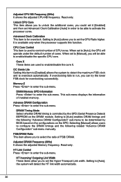
... overclocking. C1E Support To enable this item to "Enabled". * Enter Windows, and select [Start]->[Settings]->[Control Panel]->[Power Options]. Start OC Stepping From (MHz) This item is used to double confirm that you set the initial base clock. Adjust CPU Ratio This item is used to red the CPU power consumption while idle. Under Cell Menu, find AMD Cool'n'Quiet, and set base clock that : * Run BIOS Setup, and select Cell Menu. And the following items will boot...
... overclocking. C1E Support To enable this item to "Enabled". * Enter Windows, and select [Start]->[Settings]->[Control Panel]->[Power Options]. Start OC Stepping From (MHz) This item is used to double confirm that you set the initial base clock. Adjust CPU Ratio This item is used to red the CPU power consumption while idle. Under Cell Menu, find AMD Cool'n'Quiet, and set base clock that : * Run BIOS Setup, and select Cell Menu. And the following items will boot...
User Guide
Page 30
... the default number of FSB/ DRAM. Adjusted DRAM Frequency (MHz) It shows the adjusted Memory frequency. Setting to overclock automatically. Read-only. When set the CPU Ratio higher. Core X These items are used to select the ratio of cores. DIMM Memory SPD Information Press to enter the sub-menu. Advance DRAM Configuration Press to enter the sub-menu. It is controlled by BIOS based on the configurations on the DRAM module. Setting to enable/disable the specific CPU core. Read...
... the default number of FSB/ DRAM. Adjusted DRAM Frequency (MHz) It shows the adjusted Memory frequency. Setting to overclock automatically. Read-only. When set the CPU Ratio higher. Core X These items are used to select the ratio of cores. DIMM Memory SPD Information Press to enter the sub-menu. Advance DRAM Configuration Press to enter the sub-menu. It is controlled by BIOS based on the configurations on the DRAM module. Setting to enable/disable the specific CPU core. Read...
User Guide
Page 31
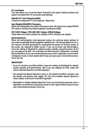
... in clock speed which may just cause your overclocked processor to adjust the voltage of CPU, Memory and chipset. But if you are overclocking because even a slight jitter can introduce a temporary boost in clock speed which may just cause your local EMI regulation. * Remember to disable Spread Spectrum if you are plagued by EMI, set the Hyper-Transport Link speed. Spread Spectrum When the motherboard's clock...
... in clock speed which may just cause your overclocked processor to adjust the voltage of CPU, Memory and chipset. But if you are overclocking because even a slight jitter can introduce a temporary boost in clock speed which may just cause your local EMI regulation. * Remember to disable Spread Spectrum if you are plagued by EMI, set the Hyper-Transport Link speed. Spread Spectrum When the motherboard's clock...
User Guide
Page 46
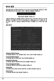
BIOS 설정 POST(Power On Self Test DEL Press DEL to enter SETUP (DEL OFF>와 , 및
BIOS 설정 POST(Power On Self Test DEL Press DEL to enter SETUP (DEL OFF>와 , 및
User Guide
Page 47
MS-7641 BIOS Setting Password BIOS Cell Menu M-Flash USB BIOS Overclocking Profile CMOS 또는 BIOS CMOS 또는 BIOS Load Fail-Safe Defaults BIOS Load Optimized Defaults BIOS Save & Exit Setup CMOS Exit Without Saving 47
MS-7641 BIOS Setting Password BIOS Cell Menu M-Flash USB BIOS Overclocking Profile CMOS 또는 BIOS CMOS 또는 BIOS Load Fail-Safe Defaults BIOS Load Optimized Defaults BIOS Save & Exit Setup CMOS Exit Without Saving 47
User Guide
Page 127
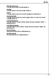
MS-7641 Cell Menu M-Flash BIOS。 Overclocking Profile BIOS CMOS或从CMOS Load Fail-Safe Defaults BIOS Load Optimized Defaults BIOS值。 Save & Exit Setup 保存对CMOS Setup程序。 Exit Without Saving 放弃对CMOS Setup程序。 127
MS-7641 Cell Menu M-Flash BIOS。 Overclocking Profile BIOS CMOS或从CMOS Load Fail-Safe Defaults BIOS Load Optimized Defaults BIOS值。 Save & Exit Setup 保存对CMOS Setup程序。 Exit Without Saving 放弃对CMOS Setup程序。 127
User Guide
Page 147
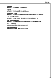
MS-7641 Cell Menu M-Flash BIOS (僅限 FAT/ FAT32 Overclocking Profile BIOS CMOS 或由 BIOS CMOS 載入。 Load Fail-Safe Defaults BIOS Load Optimized Defaults BIOS Save & Exit Setup CMOS Exit Without Saving 147
MS-7641 Cell Menu M-Flash BIOS (僅限 FAT/ FAT32 Overclocking Profile BIOS CMOS 或由 BIOS CMOS 載入。 Load Fail-Safe Defaults BIOS Load Optimized Defaults BIOS Save & Exit Setup CMOS Exit Without Saving 147
User Guide
Page 166
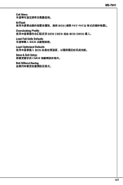
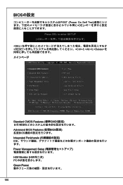
BIOSの設定 POST (Power On Self Test DEL Press DEL to enter SETUP (とと
BIOSの設定 POST (Power On Self Test DEL Press DEL to enter SETUP (とと

