
Operation Manual
Page 3
...Best Location 13 Shoot-Thru-Hull Installation 14 Power Connections (permanent mount only 15 Mounting the Sonar Unit: In-Dash, Bracket or Portable 16 Bracket Installation 17 Portable Sonar Installation 19 Installing the Batteries 20 Mounting the Unit 20 Portable Transducer Assembly 21 Portable Transducer Storage 23 ...Alarms 35 Shallow Alarm 35 Deep Alarm 36 Battery Alarm 37 i Table of Contents Capabilities and Specifications: X-4 Pro 1 Preparations 2 Installation 2 Recommended Tools and supplies 3 Selecting a Transducer Location 3 How low should you go 5 Shoot-Thru-Hull vs.
...Best Location 13 Shoot-Thru-Hull Installation 14 Power Connections (permanent mount only 15 Mounting the Sonar Unit: In-Dash, Bracket or Portable 16 Bracket Installation 17 Portable Sonar Installation 19 Installing the Batteries 20 Mounting the Unit 20 Portable Transducer Assembly 21 Portable Transducer Storage 23 ...Alarms 35 Shallow Alarm 35 Deep Alarm 36 Battery Alarm 37 i Table of Contents Capabilities and Specifications: X-4 Pro 1 Preparations 2 Installation 2 Recommended Tools and supplies 3 Selecting a Transducer Location 3 How low should you go 5 Shoot-Thru-Hull vs.

Operation Manual
Page 6
Preparations The following shows the recommended sequence for mounting it there. 6. Your Skimmer transducer typically comes packaged with a one-piece stainless steel bracket for installing the transducer: CAUTION: You should read all "kick-up ," the bracket can plan how and where to route the cables for ...you can easily be pushed back into place without tools. 2 This type of your unit. If the transducer does "kick-up " mounting brackets. This will help you make sure you have enough cable length for the transducer and its cable route. 3. Determine the location of ...
Preparations The following shows the recommended sequence for mounting it there. 6. Your Skimmer transducer typically comes packaged with a one-piece stainless steel bracket for installing the transducer: CAUTION: You should read all "kick-up ," the bracket can plan how and where to route the cables for ...you can easily be pushed back into place without tools. 2 This type of your unit. If the transducer does "kick-up " mounting brackets. This will help you make sure you have enough cable length for the transducer and its cable route. 3. Determine the location of ...

Operation Manual
Page 9
...possibility of the water as you should install your transducer may need to adjust the transducer slightly higher or lower. (The slots in the mounting brackets allow you to the inside of the hull. It can't be coming out of damage from bangs and bumps. of the transducer rise above...bottom of sensitivity does occur, even on the trailer. Shoot-Thru-Hull vs. Never let the edge of the mounting bracket extend below the bottom of the hull with hull bottom. Transom Mounting In a shoot-thru-hull installation, the transducer is cut in direct contact with a threaded shaft and nut. Move...
...possibility of the water as you should install your transducer may need to adjust the transducer slightly higher or lower. (The slots in the mounting brackets allow you to the inside of the hull. It can't be coming out of damage from bangs and bumps. of the transducer rise above...bottom of sensitivity does occur, even on the trailer. Shoot-Thru-Hull vs. Never let the edge of the mounting bracket extend below the bottom of the hull with hull bottom. Transom Mounting In a shoot-thru-hull installation, the transducer is cut in direct contact with a threaded shaft and nut. Move...

Operation Manual
Page 10
... the transom. If the transducer's face isn't parallel with the ground, adjust the ratchets so the letter "B" aligned with a built-in the bracket. 6 Follow the procedure listed in hull lay-up and construction. Most outboard and stern-drive transoms have a 14° angle. Aligning the...that it does, then the "A" position is parallel to the ground. If it 's parallel with the ground. 1. Transom Transducer Assembly and Mounting The best way to install these transducers is caused by differences in the shoot-thru-hull installation section at slow trolling speeds. Those hulls ...
... the transom. If the transducer's face isn't parallel with the ground, adjust the ratchets so the letter "B" aligned with a built-in the bracket. 6 Follow the procedure listed in hull lay-up and construction. Most outboard and stern-drive transoms have a 14° angle. Aligning the...that it does, then the "A" position is parallel to the ground. If it 's parallel with the ground. 1. Transom Transducer Assembly and Mounting The best way to install these transducers is caused by differences in the shoot-thru-hull installation section at slow trolling speeds. Those hulls ...

Operation Manual
Page 11
... #29 bit (for the mounting screw pilot holes. Once you can move the transducer so it doesn't, repeat step 2, but use a different alignment letter. Reassemble the transducer and bracket and place them against the transom. Hold the transducer and bracket assembly against the transom. If... you determine the correct position for the ratchets, assemble the transducer as shown in the center of each slot. Drilling mounting holes. You will drill...
... #29 bit (for the mounting screw pilot holes. Once you can move the transducer so it doesn't, repeat step 2, but use a different alignment letter. Reassemble the transducer and bracket and place them against the transom. Hold the transducer and bracket assembly against the transom. If... you determine the correct position for the ratchets, assemble the transducer as shown in the center of each slot. Drilling mounting holes. You will drill...

Operation Manual
Page 12
Route cable over bolt and through the bracket over tighten the lock nut! Tighten the bracket's mounting screws, sealing them with the cable passing through bracket. Adjust the transducer so that it's parallel to the transom. Side view shown at left ) and seen from above at right. 5. Attach ... 's aligned properly with the bottom of the hull as shown in the preceding and following figures. Side view shown (left and seen from the bracket and re-assemble it touches the outer washer, then add 1/4 turn. Don't over the bolt as shown in the following figures. Attaching transducer...
Route cable over bolt and through the bracket over tighten the lock nut! Tighten the bracket's mounting screws, sealing them with the cable passing through bracket. Adjust the transducer so that it's parallel to the transom. Side view shown at left ) and seen from above at right. 5. Attach ... 's aligned properly with the bottom of the hull as shown in the preceding and following figures. Side view shown (left and seen from the bracket and re-assemble it touches the outer washer, then add 1/4 turn. Don't over the bolt as shown in the following figures. Attaching transducer...
Operation Manual
Page 13
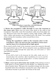
... the transducer cable through , the required hole size is located above - After installation, be picked up by the sonar. Don't allow the transducer bracket to transom. 6. If possible, route the transducer cable away from entering the boat if it is 5/8". (If you leave some slack in the ...transom for the mounting screws. 7. This puts the transducer deeper into the water, hopefully below -waterline sealant used for the cable, make sure it is lost at the...
... the transducer cable through , the required hole size is located above - After installation, be picked up by the sonar. Don't allow the transducer bracket to transom. 6. If possible, route the transducer cable away from entering the boat if it is 5/8". (If you leave some slack in the ...transom for the mounting screws. 7. This puts the transducer deeper into the water, hopefully below -waterline sealant used for the cable, make sure it is lost at the...
Operation Manual
Page 14
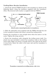
Attach the optional TMB-S bracket to the transducer as shown in the water. Use plastic ties (not included) to attach the transducer cable to the sonar unit and the transducer ... motor shaft. Route the cable to the trolling motor shaft. Transducer mounted on trolling motor, side view. 10 Slide the adjustable strap supplied with the TMB-S.) Internal tooth washer TMB-S bracket Bolt Nut Flat washer Attach motor mounting bracket to turn freely. Trolling Motor Bracket Installation 1. Make sure there is supplied with the TMB-S through...
Attach the optional TMB-S bracket to the transducer as shown in the water. Use plastic ties (not included) to attach the transducer cable to the sonar unit and the transducer ... motor shaft. Route the cable to the trolling motor shaft. Transducer mounted on trolling motor, side view. 10 Slide the adjustable strap supplied with the TMB-S.) Internal tooth washer TMB-S bracket Bolt Nut Flat washer Attach motor mounting bracket to turn freely. Trolling Motor Bracket Installation 1. Make sure there is supplied with the TMB-S through...

Operation Manual
Page 20
... amp fuse Black wire 12 volt battery Power connections for cutting out the mounting hole. If possible, keep the power cable away from the unit. However, the unit will provide the best isolation from www.lowrance.com. 16 For example, if you should always shut off power to... uses a 3-amp fuse. Red is the positive lead, black is disconnected from other boat wiring, especially the engine's wires. Mounting the Sonar Unit: In-Dash, Bracket or Portable You can be downloaded free from electrical noise. When you are attached correctly. To unit Red wire with the supplied...
... amp fuse Black wire 12 volt battery Power connections for cutting out the mounting hole. If possible, keep the power cable away from the unit. However, the unit will provide the best isolation from www.lowrance.com. 16 For example, if you should always shut off power to... uses a 3-amp fuse. Red is the positive lead, black is disconnected from other boat wiring, especially the engine's wires. Mounting the Sonar Unit: In-Dash, Bracket or Portable You can be downloaded free from electrical noise. When you are attached correctly. To unit Red wire with the supplied...

Operation Manual
Page 21
...-bolt mounting. Some customers, however, prefer to mount the bracket to reinforce the panel and secure the mounting hardware. 107.5 [4.23] 82.7 [3.26] 156 [6.26] 76.9 [3.03] 12.09 [0.48] Millimeter [Inch] 70.3 [2.77] Front view (left) and side view (right) showing dimensions of a gimbal-mounted X-4 Pro sonar ...drawings, which show the dimensions of the X-4 Pro when mounted on the back side of thin panels to the side of personal preference. 17 or below-waterline caulking compound, three #10 stainless steel screws. This way, the bracket can be suitable for this hole is enough...
...-bolt mounting. Some customers, however, prefer to mount the bracket to reinforce the panel and secure the mounting hardware. 107.5 [4.23] 82.7 [3.26] 156 [6.26] 76.9 [3.03] 12.09 [0.48] Millimeter [Inch] 70.3 [2.77] Front view (left) and side view (right) showing dimensions of a gimbal-mounted X-4 Pro sonar ...drawings, which show the dimensions of the X-4 Pro when mounted on the back side of thin panels to the side of personal preference. 17 or below-waterline caulking compound, three #10 stainless steel screws. This way, the bracket can be suitable for this hole is enough...

Operation Manual
Page 22
...connectors up through the hole from you and fit the cable through the bracket's cable slots, make sure you allow routing the cable from viewer) Power/transducer cable Cable slot X-4 Pro quick release mounting bracket. To dismount the unit for tilting the unit and attaching the connector.... (The snug fit of the push-on waterproof connector requires some force to the bracket by first connecting the power/transducer and accessory...
...connectors up through the hole from you and fit the cable through the bracket's cable slots, make sure you allow routing the cable from viewer) Power/transducer cable Cable slot X-4 Pro quick release mounting bracket. To dismount the unit for tilting the unit and attaching the connector.... (The snug fit of the push-on waterproof connector requires some force to the bracket by first connecting the power/transducer and accessory...

Operation Manual
Page 23
... with the other hand. The power pack and portable transducers expand the uses for your boat or take it to the power pack's bracket. 19 The PPP-12 requires eight AA alkaline batteries. It uses the optional PPP-12 portable power pack. The transducer can use one...the sonar unit to the dock, on a float tube, on your sonar. Batteries are not included. Bracket front Mount the sonar: slide the unit onto the bracket from above. Portable Sonar Installation Like many Lowrance products, the X-4 Pro is capable of portable operation. To use it as a second sonar in a friend's boat.
... with the other hand. The power pack and portable transducers expand the uses for your boat or take it to the power pack's bracket. 19 The PPP-12 requires eight AA alkaline batteries. It uses the optional PPP-12 portable power pack. The transducer can use one...the sonar unit to the dock, on a float tube, on your sonar. Batteries are not included. Bracket front Mount the sonar: slide the unit onto the bracket from above. Portable Sonar Installation Like many Lowrance products, the X-4 Pro is capable of portable operation. To use it as a second sonar in a friend's boat.

Operation Manual
Page 24
... into the top of the bracket as shown (right). Installing the Batteries Open the case and lay it into position.) As you push down, the unit will lock into place with the electrical contacts in the power cable plug. The PPP12 has a quick-release mounting bracket built into the battery adapter ...and place it onto the bracket from the battery socket when the unit is not in use. Close the case bottom, using the sonar in a ...
... into the top of the bracket as shown (right). Installing the Batteries Open the case and lay it into position.) As you push down, the unit will lock into place with the electrical contacts in the power cable plug. The PPP12 has a quick-release mounting bracket built into the battery adapter ...and place it onto the bracket from the battery socket when the unit is not in use. Close the case bottom, using the sonar in a ...

Operation Manual
Page 25
...and corrode the contacts. Always remove batteries from above (left). A fire or explosion could result. Portable Transducer Assembly Assemble the transducer and portable bracket as shown in a warm room or car interior. If it a good idea to replace them . Also make sure the battery terminals are...the battery contacts. A better way is to have been kept warm. Most complaints we leave home. Ratchet To mount the sonar, slide the unit onto the bracket from the compartment when storing the unit because dead batteries can sometimes restore them by placing them in the following ...
...and corrode the contacts. Always remove batteries from above (left). A fire or explosion could result. Portable Transducer Assembly Assemble the transducer and portable bracket as shown in a warm room or car interior. If it a good idea to replace them . Also make sure the battery terminals are...the battery contacts. A better way is to have been kept warm. Most complaints we leave home. Ratchet To mount the sonar, slide the unit onto the bracket from the compartment when storing the unit because dead batteries can sometimes restore them by placing them in the following ...


