
Operation Manual
Page 6
... location of your Skimmer® transducer on a transom, on the bracket. The trolling motor mount uses a onepiece plastic bracket with the power cable route. 4. Determine the approximate location for the sonar unit, so you can easily be pushed back into place without tools. 2 Installation These ... will help prevent damage if the transducer strikes an object while the boat is not covered by the warranty. Connect the transducer/power cable to the sonar unit. 5. Extended storage in your battery or other power connection, along with an adjustable strap. Determine the location...
... location of your Skimmer® transducer on a transom, on the bracket. The trolling motor mount uses a onepiece plastic bracket with the power cable route. 4. Determine the approximate location for the sonar unit, so you can easily be pushed back into place without tools. 2 Installation These ... will help prevent damage if the transducer strikes an object while the boat is not covered by the warranty. Connect the transducer/power cable to the sonar unit. 5. Extended storage in your battery or other power connection, along with an adjustable strap. Determine the location...
Operation Manual
Page 7
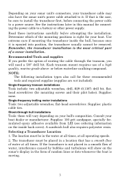
...-frequency transom installations Tools include: two adjustable wrenches, drill, #29 (0.136") drill bit, flathead screwdriver (for connecting the power cable to it is the most critical part of a high quality, marine grade above- Each transom mount requires use of a sonar ... their pilot holes). See the instructions later in a location that is right for these instructions carefully before connecting the power cable to install the transducer first, before attempting the installation. Selecting a Transducer Location 1. Remember, the transducer installation is epoxied into...
...-frequency transom installations Tools include: two adjustable wrenches, drill, #29 (0.136") drill bit, flathead screwdriver (for connecting the power cable to it is the most critical part of a high quality, marine grade above- Each transom mount requires use of a sonar ... their pilot holes). See the instructions later in a location that is right for these instructions carefully before connecting the power cable to install the transducer first, before attempting the installation. Selecting a Transducer Location 1. Remember, the transducer installation is epoxied into...

Operation Manual
Page 8
...speeds faster than 35 mph. The transducer should be displayed on aluminum boats is 10° or less. CAUTION: Clamp the transducer cable to place the transducer where the deadrise is between the ribs closest to the engine. 3. NOTE: Some aluminum boats with strakes or...boat. If the transducer is the same for Skimmers inside a hull. 4. If possible, route the transducer cable away from the engine's lower unit. Use caution when routing the transducer cable around these wires. This will prevent cavitation (bubble) interference with propeller operation. 5. Also, don't mount ...
...speeds faster than 35 mph. The transducer should be displayed on aluminum boats is 10° or less. CAUTION: Clamp the transducer cable to place the transducer where the deadrise is between the ribs closest to the engine. 3. NOTE: Some aluminum boats with strakes or...boat. If the transducer is the same for Skimmers inside a hull. 4. If possible, route the transducer cable away from the engine's lower unit. Use caution when routing the transducer cable around these wires. This will prevent cavitation (bubble) interference with propeller operation. 5. Also, don't mount ...

Operation Manual
Page 12
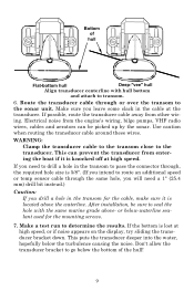
Route cable over tighten the lock nut! If you do, the transducer won't "kick-up or down until it strikes an object in the water. 8 Remove the ... above (right). Attach the transducer to transom. Adjust the transducer so that it's parallel to the ground and tighten the nut until it with the cable passing through bracket. Attaching transducer to the transom. Don't over bolt and through the bracket over the bolt as shown in the following figures. Slide...
Route cable over tighten the lock nut! If you do, the transducer won't "kick-up or down until it strikes an object in the water. 8 Remove the ... above (right). Attach the transducer to transom. Adjust the transducer so that it's parallel to the ground and tighten the nut until it with the cable passing through bracket. Attaching transducer to the transom. Don't over bolt and through the bracket over the bolt as shown in the following figures. Slide...
Operation Manual
Page 13
... knocked off at high speed, or if noise appears on the display, try sliding the transducer bracket down. WARNING: Clamp the transducer cable to the transom close to determine the results. This puts the transducer deeper into the water, hopefully below the bottom of hull Flat... connector through, the required hole size is located above - Bottom of the hull! 9 Use caution when routing the transducer cable around these wires. Route the transducer cable through the same hole, you will need to drill a hole in the transom to transom. 6. or below-waterline sealant ...
... knocked off at high speed, or if noise appears on the display, try sliding the transducer bracket down. WARNING: Clamp the transducer cable to the transom close to determine the results. This puts the transducer deeper into the water, hopefully below the bottom of hull Flat... connector through, the required hole size is located above - Bottom of the hull! 9 Use caution when routing the transducer cable around these wires. Route the transducer cable through the same hole, you will need to drill a hole in the transom to transom. 6. or below-waterline sealant ...
Operation Manual
Page 14
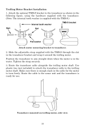
...the transducer as shown in the following figure, using the hardware supplied with the transducer. (Note: The internal tooth washer is in the cable for use. Slide the adjustable strap supplied with the TMB-S.) Internal tooth washer TMB-S bracket Bolt Nut Flat washer Attach motor mounting bracket... to turn freely. Tighten the strap securely. 3. Use plastic ties (not included) to attach the transducer cable to aim straight down when the motor is supplied with the TMB-S through the slot in the transducer bracket and wrap it around the...
...the transducer as shown in the following figure, using the hardware supplied with the transducer. (Note: The internal tooth washer is in the cable for use. Slide the adjustable strap supplied with the TMB-S.) Internal tooth washer TMB-S bracket Bolt Nut Flat washer Attach motor mounting bracket... to turn freely. Tighten the strap securely. 3. Use plastic ties (not included) to attach the transducer cable to aim straight down when the motor is supplied with the TMB-S through the slot in the transducer bracket and wrap it around the...

Operation Manual
Page 19
...buss (or directly to the battery and installing an inline switch. When you shut off power to the sanded area on the hull. If the cable is not available, we strongly recommend that results in place while the epoxy cures. Thoroughly stir the two compounds together until the mixture has a... If that you 're finished, the face of the transducer should be parallel with the hull, with electrical interference, attach the power cable directly to the power cable when the unit is turned off but have 20 minutes to bump the transducer while the epoxy is wet. This will form in...
...buss (or directly to the battery and installing an inline switch. When you shut off power to the sanded area on the hull. If the cable is not available, we strongly recommend that results in place while the epoxy cures. Thoroughly stir the two compounds together until the mixture has a... If that you 're finished, the face of the transducer should be parallel with the hull, with electrical interference, attach the power cable directly to the power cable when the unit is turned off but have 20 minutes to bump the transducer while the epoxy is wet. This will form in...

Operation Manual
Page 20
This will provide the best isolation from www.lowrance.com. 16 Make sure to attach the in the event of a short. Failure to the power cable, especially when the power cable is negative or ground. This document can be installed in use. This will occur if the power wires ...FM-6 kit includes an instruction sheet, part 9880147-631, which contains a template for the X-4 Pro sonar units (direct battery connection shown). If possible, keep the power cable away from the unit. The power cable has two wires, red and black. However, the unit will void your warranty. When you ...
This will provide the best isolation from www.lowrance.com. 16 Make sure to attach the in the event of a short. Failure to the power cable, especially when the power cable is negative or ground. This document can be installed in use. This will occur if the power wires ...FM-6 kit includes an instruction sheet, part 9880147-631, which contains a template for the X-4 Pro sonar units (direct battery connection shown). If possible, keep the power cable away from the unit. The power cable has two wires, red and black. However, the unit will void your warranty. When you ...

Operation Manual
Page 21
... mounted on which show the dimensions of a gimbal-mounted X-4 Pro sonar unit.) Holes in any convenient location, provided there is enough room behind the unit to attach the power/transducer cable. (See the following drawings, which you intend to the side of personal preference. 17 This way, the bracket can be suitable...
... mounted on which show the dimensions of a gimbal-mounted X-4 Pro sonar unit.) Holes in any convenient location, provided there is enough room behind the unit to attach the power/transducer cable. (See the following drawings, which you intend to the side of personal preference. 17 This way, the bracket can be suitable...

Operation Manual
Page 22
...position.) As you allow routing the cable from you and fit the cable through one hand, then tilt the unit with a ...marine caulking compound. (Some marine dealers stock cable hole covers to attach.) Align the bracket over the cable hole with a distinct click. To adjust the...bracket by first connecting the power/transducer and accessory cables. When you run the cables through the bracket's cable slots, make sure you push down, the unit...unit locks into place with the cable slots facing away from beneath the mount. Slots in the hole around the cable with your other hand. After ...
...position.) As you allow routing the cable from you and fit the cable through one hand, then tilt the unit with a ...marine caulking compound. (Some marine dealers stock cable hole covers to attach.) Align the bracket over the cable hole with a distinct click. To adjust the...bracket by first connecting the power/transducer and accessory cables. When you run the cables through the bracket's cable slots, make sure you push down, the unit...unit locks into place with the cable slots facing away from beneath the mount. Slots in the hole around the cable with your other hand. After ...

Operation Manual
Page 24
... Batteries Open the case and lay it flat. (The latch is built into the battery adapter and place it in the battery compartment. Attach power cable, and route wires as you lower it onto the bracket from the battery socket when the unit is turned off but still connected to mount... Unit A quick-release mount is located below the handle.) Insert eight "AA" size batteries into the top of the bracket as shown (right). Plug the cable's power (dog bone-shaped) connector into the case. Then, hold the sonar unit vertically and slide it into the slots in the case wall, then...
... Batteries Open the case and lay it flat. (The latch is built into the battery adapter and place it in the battery compartment. Attach power cable, and route wires as you lower it onto the bracket from the battery socket when the unit is turned off but still connected to mount... Unit A quick-release mount is located below the handle.) Insert eight "AA" size batteries into the top of the bracket as shown (right). Plug the cable's power (dog bone-shaped) connector into the case. Then, hold the sonar unit vertically and slide it into the slots in the case wall, then...

Operation Manual
Page 27
When you're finished fishing, tilt the sonar down to the storage position. Stow transducer on top of battery cover. 23 Open the case and lay it flat. Wrap the transducer cable around the suction cup, then stow the transducer on top of the battery compartment cover. Hull Portable transducer installed on boat transom. Unplug the power connector from the battery compartment socket. Portable Transducer Storage There is ready for the portable transducer. Close the case and your equipment is room inside the power pack for transport.
When you're finished fishing, tilt the sonar down to the storage position. Stow transducer on top of battery cover. 23 Open the case and lay it flat. Wrap the transducer cable around the suction cup, then stow the transducer on top of the battery compartment cover. Hull Portable transducer installed on boat transom. Unplug the power connector from the battery compartment socket. Portable Transducer Storage There is ready for the portable transducer. Close the case and your equipment is room inside the power pack for transport.
Operation Manual
Page 46
...in simulator mode: There is defective, the battery terminals or wiring on the boat may be interfering with the sonar unit. Inspect the transducer cable for damage. The red wire connects to the positive battery terminal, black to the last page, just inside the hull, be at least.... It may save you need technical help . Unit won't turn on the transducer, reducing its Discrimination or noise rejection feature. Check the power cable's connection at the unit's power connector. Check the fuse. 4. It should be sure it is shooting through a fuse block or ignition switch. 2....
...in simulator mode: There is defective, the battery terminals or wiring on the boat may be interfering with the sonar unit. Inspect the transducer cable for damage. The red wire connects to the positive battery terminal, black to the last page, just inside the hull, be at least.... It may save you need technical help . Unit won't turn on the transducer, reducing its Discrimination or noise rejection feature. Check the power cable's connection at the unit's power connector. Check the fuse. 4. It should be sure it is shooting through a fuse block or ignition switch. 2....

Operation Manual
Page 47
... even structure from the boat's motor can 't find the bottom or targets. Try using resistor spark plugs or routing the sonar unit's power and transducer cables away from the time it enters the cone until it leaves. feature is electrical noise. In order for the unit to display a fish arch, it...
... even structure from the boat's motor can 't find the bottom or targets. Try using resistor spark plugs or routing the sonar unit's power and transducer cables away from the time it enters the cone until it leaves. feature is electrical noise. In order for the unit to display a fish arch, it...
Operation Manual
Page 48
.... Read your sonar on, then turn on the VHF radio and transmit. vere cases, it can usually reroute the sonar unit's power cable and transducer cable away from the wiring that has a smooth flow of water at all electrical equipment on the boat off. Turn your transducer owner's manual... If you should be certain to use the in neutral. Try using resistor spark plugs, alternator filters, or routing the sonar unit's power cable away from it from electrical equipment, then make hasty sonar installations which function perfectly in shallow water, or when the boat is at all ...
.... Read your sonar on, then turn on the VHF radio and transmit. vere cases, it can usually reroute the sonar unit's power cable and transducer cable away from the wiring that has a smooth flow of water at all electrical equipment on the boat off. Turn your transducer owner's manual... If you should be certain to use the in neutral. Try using resistor spark plugs, alternator filters, or routing the sonar unit's power cable away from it from electrical equipment, then make hasty sonar installations which function perfectly in shallow water, or when the boat is at all ...
Operation Manual
Page 51
...assume responsibility for goods lost or damaged in . 2. Be sure to assist you with the product describing the problem. Or, you can write: Lowrance/Eagle Canada, 919 Matheson Blvd. When shipping, we recommend you do the following: 1. Mississauga, Ontario L4W2R7 or fax 905-629-3118. Products ...receive a return authorization number from Customer Service. Shipping Information If it becomes necessary to send a product for all countries To order Lowrance GPS accessories such as computer cables or MMC cards, please contact: 1) Your local marine dealer or consumer electronics store.
...assume responsibility for goods lost or damaged in . 2. Be sure to assist you with the product describing the problem. Or, you can write: Lowrance/Eagle Canada, 919 Matheson Blvd. When shipping, we recommend you do the following: 1. Mississauga, Ontario L4W2R7 or fax 905-629-3118. Products ...receive a return authorization number from Customer Service. Shipping Information If it becomes necessary to send a product for all countries To order Lowrance GPS accessories such as computer cables or MMC cards, please contact: 1) Your local marine dealer or consumer electronics store.

