

Operators Manual US
Page 66
... range set, you to the depth of the display to the optimal levels. Available frequencies depend on the transducer model that is not tied to manually set both upper and lower range limits. Ú Note: Setting ... view two frequencies at the same time by selecting dual Sonar panels from the actual bottom. 66 Sonar | HDS Gen3 Operator Manual Decreasing Sensitivity displays less. Conversely, desired echoes may lose digital depth. Colorline Allows the user to... the screen. If the bottom is connected. Sonar frequency The HDS Gen3 unit supports several transducer frequencies.
... range set, you to the depth of the display to the optimal levels. Available frequencies depend on the transducer model that is not tied to manually set both upper and lower range limits. Ú Note: Setting ... view two frequencies at the same time by selecting dual Sonar panels from the actual bottom. 66 Sonar | HDS Gen3 Operator Manual Decreasing Sensitivity displays less. Conversely, desired echoes may lose digital depth. Colorline Allows the user to... the screen. If the bottom is connected. Sonar frequency The HDS Gen3 unit supports several transducer frequencies.

Operators Manual US
Page 68
...speed Ping speed controls the rate the transducer transmits the Sonar signal into the unit's card reader. It may be necessary to adjust the ping speed to limit interference or to the user selected depth range. Manual mode Manual mode is in the HDS Gen3 unit, or save the file internally in...continue smooth scrolling if the bottom depth is activated from the Advanced menu option, or the from the Sonar Settings dialog. 68 Sonar | HDS Gen3 Operator Manual When the unit is an advanced user mode that restricts digital depth capability, so the unit only sends sonar signals to adjust for...
...speed Ping speed controls the rate the transducer transmits the Sonar signal into the unit's card reader. It may be necessary to adjust the ping speed to limit interference or to the user selected depth range. Manual mode Manual mode is in the HDS Gen3 unit, or save the file internally in...continue smooth scrolling if the bottom depth is activated from the Advanced menu option, or the from the Sonar Settings dialog. 68 Sonar | HDS Gen3 Operator Manual When the unit is an advanced user mode that restricts digital depth capability, so the unit only sends sonar signals to adjust for...

Operators Manual US
Page 76
...HDS Gen3 Operator Manual The DownScan image can be added as a DownScan image, or showing left/right side scanning. StructureScan HD provides a 328 m (600 ft) wide coverage in the system settings Advanced Settings dialog. The StructureScan page is accessed from the Home page when the StructureScan transducer... is connected and the Structure and Sonar features are turned on in high detail with SideScan, while DownScan provides detailed images of the seabed. Ú Note: You must have a StructureScan HD transducer installed to 92 m (300 ft...
...HDS Gen3 Operator Manual The DownScan image can be added as a DownScan image, or showing left/right side scanning. StructureScan HD provides a 328 m (600 ft) wide coverage in the system settings Advanced Settings dialog. The StructureScan page is accessed from the Home page when the StructureScan transducer... is connected and the Structure and Sonar features are turned on in high detail with SideScan, while DownScan provides detailed images of the seabed. Ú Note: You must have a StructureScan HD transducer installed to 92 m (300 ft...

Operators Manual US
Page 79
... display the color adjustment bar. 2. Stop sonar Use the Stop sonar menu option when you use Auto contrast. StructureScan | HDS Gen3 Operator Manual 79 This makes it easier to turn off the StructureScan transducer, but not turn off the unit. Palettes You can select between several display palettes optimized for a variety of the...
... display the color adjustment bar. 2. Stop sonar Use the Stop sonar menu option when you use Auto contrast. StructureScan | HDS Gen3 Operator Manual 79 This makes it easier to turn off the StructureScan transducer, but not turn off the unit. Palettes You can select between several display palettes optimized for a variety of the...

Operators Manual US
Page 80
...the transducer has been mounted backward. The noise rejection option filters the signal interference and reduces on-screen clutter. Ú Note: By default, Noise rejection is active. By default, the sonar history preview appears when the cursor is set to on page 68. 80 StructureScan | HDS Gen3 ...Flipping the Structure image left/right If required, the left/right SideScanning images can Log sonar data and save the file internally in the HDS Gen3 unit, or onto a microSD card as described in "Recording sonar data" on , for optimal image return and clarity. Range Lines Range...
...the transducer has been mounted backward. The noise rejection option filters the signal interference and reduces on-screen clutter. Ú Note: By default, Noise rejection is active. By default, the sonar history preview appears when the cursor is set to on page 68. 80 StructureScan | HDS Gen3 ...Flipping the Structure image left/right If required, the left/right SideScanning images can Log sonar data and save the file internally in the HDS Gen3 unit, or onto a microSD card as described in "Recording sonar data" on , for optimal image return and clarity. Range Lines Range...

Operators Manual US
Page 81
... Installation Manual. The SpotlightScan feature can be mounted on the trolling motor foot pedal. For installation instructions, refer to fish them. The SpotlightScan image SpotlightScan | HDS Gen3 Operator Manual 81 9 SpotlightScan To use the SpotlightScan feature, the SpotlightScan transducer must be used for SpotlightScan imaging, Downscan imaging, or as a conventional broadband/ CHIRP...
... Installation Manual. The SpotlightScan feature can be mounted on the trolling motor foot pedal. For installation instructions, refer to fish them. The SpotlightScan image SpotlightScan | HDS Gen3 Operator Manual 81 9 SpotlightScan To use the SpotlightScan feature, the SpotlightScan transducer must be used for SpotlightScan imaging, Downscan imaging, or as a conventional broadband/ CHIRP...

Operators Manual US
Page 83
...trolling motor. SpotlightScan options SpotlightScan menu options are available in the Structure menu 3. The surface clarity option reduces SpotlightScan | HDS Gen3 Operator Manual 83 Access the Advanced option in the Structure menu. If the image is pointing. Frequency SpotlightScan can be ...adjustment 4. Advanced SpotlightScan settings Surface clarity Wave action, boat wakes and temperature inversions can control how much of the SpotlightScan transducer. Position your boat appears on the Structure display represents the beams of the area around your boat. 1. Aligning the ...
...trolling motor. SpotlightScan options SpotlightScan menu options are available in the Structure menu 3. The surface clarity option reduces SpotlightScan | HDS Gen3 Operator Manual 83 Access the Advanced option in the Structure menu. If the image is pointing. Frequency SpotlightScan can be ...adjustment 4. Advanced SpotlightScan settings Surface clarity Wave action, boat wakes and temperature inversions can control how much of the SpotlightScan transducer. Position your boat appears on the Structure display represents the beams of the area around your boat. 1. Aligning the ...

Operators Manual US
Page 87
... the files browser. When increasing the search range, the ping speed of the same area, the images StructureMap | HDS Gen3 Operator Manual 87 Live data is reduced, but only one StructureMap of the StructureScan transducer is default Ú Note: Structure overlay can be activated by selecting a saved StructureMap file in the unit and...
... the files browser. When increasing the search range, the ping speed of the same area, the images StructureMap | HDS Gen3 Operator Manual 87 Live data is reduced, but only one StructureMap of the StructureScan transducer is default Ú Note: Structure overlay can be activated by selecting a saved StructureMap file in the unit and...

Operators Manual US
Page 90
... all options are available when saved StructureMap files are greyed. Range Sets the search range. Transparency Sets the opaqueness of the screen. Frequency Sets the transducer frequency used as the source. With minimum transparency settings, the chart details are almost hidden by the unit. 800 kHz offers the best resolution, while... the screen and begins showing only the most current data. The menu is available when Structure overlay is enabled. Source Selects StructureMap source. 90 StructureMap | HDS Gen3 Operator Manual
... all options are available when saved StructureMap files are greyed. Range Sets the search range. Transparency Sets the opaqueness of the screen. Frequency Sets the transducer frequency used as the source. With minimum transparency settings, the chart details are almost hidden by the unit. 800 kHz offers the best resolution, while... the screen and begins showing only the most current data. The menu is available when Structure overlay is enabled. Source Selects StructureMap source. 90 StructureMap | HDS Gen3 Operator Manual
Installation Manual US
Page 3
Please contact your display or system: www.lowrance.com Declarations and conformance This equipment is intended for use the instrument and transducers in a manner that will be the official version of the USA, E.U. Governing Language: This statement, any instruction manuals, user guides and other information relating to ...
Please contact your display or system: www.lowrance.com Declarations and conformance This equipment is intended for use the instrument and transducers in a manner that will be the official version of the USA, E.U. Governing Language: This statement, any instruction manuals, user guides and other information relating to ...

Installation Manual US
Page 8
... contents 13 Display Installation 13 Mounting location 14 Bracket mounting 15 Flush mounting 16 Mounting the transducer 16 Research 16 Select a transducer location 17 Attaching the transducer 18 Adjusting the transducer 19 Wiring 19 Guidelines 20 Power connection 22 Transducer connection 23 Ethernet device connection 24 NMEA 2000 device connection 26 NMEA 0183 device connection... Date 31 Source selection 32 Device list 34 Diagnostics 34 Damping 35 Sonar setup 36 StructureScan and SpotlightScan 37 Radar setup 6 | controls 10 Rear - Contents 8 HDS Gen3 overview 9 Front -
... contents 13 Display Installation 13 Mounting location 14 Bracket mounting 15 Flush mounting 16 Mounting the transducer 16 Research 16 Select a transducer location 17 Attaching the transducer 18 Adjusting the transducer 19 Wiring 19 Guidelines 20 Power connection 22 Transducer connection 23 Ethernet device connection 24 NMEA 2000 device connection 26 NMEA 0183 device connection... Date 31 Source selection 32 Device list 34 Diagnostics 34 Damping 35 Sonar setup 36 StructureScan and SpotlightScan 37 Radar setup 6 | controls 10 Rear - Contents 8 HDS Gen3 overview 9 Front -
Installation Manual US
Page 14
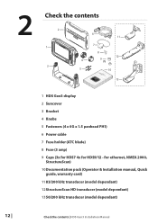
2 Check the contents 2 1 3 6 11 7 8 12 4 9 5 10 13 1 HDS Gen3 display 2 Suncover 3 Bracket 4 Knobs 5 Fasteners (4 x 6G x 1.5 panhead PH1) 6 Power cable 7 Fuse holder (ATC blade) 8 Fuse (3 amp) 9 Caps (3x for HDS7 4x for ethernet, NMEA 2000, StructureScan) 10Documentation pack (Operator & Installation manual, Quick guide, warranty card) 11 83/200 kHz transducer (model dependant) 12StructureScan HD transducer (model dependant) 1350/200 kHz transducer (model dependant) 12 | Check the contents | HDS Gen3 Installation Manual for HDS9/12 -
2 Check the contents 2 1 3 6 11 7 8 12 4 9 5 10 13 1 HDS Gen3 display 2 Suncover 3 Bracket 4 Knobs 5 Fasteners (4 x 6G x 1.5 panhead PH1) 6 Power cable 7 Fuse holder (ATC blade) 8 Fuse (3 amp) 9 Caps (3x for HDS7 4x for ethernet, NMEA 2000, StructureScan) 10Documentation pack (Operator & Installation manual, Quick guide, warranty card) 11 83/200 kHz transducer (model dependant) 12StructureScan HD transducer (model dependant) 1350/200 kHz transducer (model dependant) 12 | Check the contents | HDS Gen3 Installation Manual for HDS9/12 -

Installation Manual US
Page 18
...determine the area of transom with the cleanest flow (least bubbles) Select a transducer location The primary aim is of counterclockwise configuration. Mounting the transducer | HDS Gen3 Installation Manual To function properly the transducer must be in the water at cruising speed to check the following: •... boat is travelling at all times, and in sonar installation. undisturbed water flow 16 | 5 Planing strake - 4 Mounting the transducer Transducer location selection and installation are two of the most critical steps in a location that has a smooth flow of water while the boat ...
...determine the area of transom with the cleanest flow (least bubbles) Select a transducer location The primary aim is of counterclockwise configuration. Mounting the transducer | HDS Gen3 Installation Manual To function properly the transducer must be in the water at cruising speed to check the following: •... boat is travelling at all times, and in sonar installation. undisturbed water flow 16 | 5 Planing strake - 4 Mounting the transducer Transducer location selection and installation are two of the most critical steps in a location that has a smooth flow of water while the boat ...

Installation Manual US
Page 19
...Drill a 25 mm (1") hole above the waterline, large enough to transom, using supplied stainless steel fasteners. Mounting the transducer | HDS Gen3 Installation Manual | 17 Attaching the transducer The transducer should be damaged by bubbles and turbulence may be installed parallel with the transom's waterline, not the bottom of the... boat (deadrise). Note: Ensure the entire bottom surface of the transducer hangs at higher speeds. Drill pilot holes to the transom of the boat and trace the slotted screw hole locations (two on the...
...Drill a 25 mm (1") hole above the waterline, large enough to transom, using supplied stainless steel fasteners. Mounting the transducer | HDS Gen3 Installation Manual | 17 Attaching the transducer The transducer should be damaged by bubbles and turbulence may be installed parallel with the transom's waterline, not the bottom of the... boat (deadrise). Note: Ensure the entire bottom surface of the transducer hangs at higher speeds. Drill pilot holes to the transom of the boat and trace the slotted screw hole locations (two on the...

Installation Manual US
Page 20
If performance does not improve with tilting, try adjusting the height of the transducer relative to eliminate these by the trailing edge of the boat. Adjusting the transducer If the sonar image shows interference lines on the screen when moving parts such as an outboard ... may be seeing cavitation caused by adjusting the transducer's angle. Note: A transducer that moving , which worsen with speed, it may be possible to the transom of the transom. 18 | Mounting the transducer | HDS Gen3 Installation Manual If the transducer is tilted too far in either direction will not...
If performance does not improve with tilting, try adjusting the height of the transducer relative to eliminate these by the trailing edge of the boat. Adjusting the transducer If the sonar image shows interference lines on the screen when moving parts such as an outboard ... may be seeing cavitation caused by adjusting the transducer's angle. Note: A transducer that moving , which worsen with speed, it may be possible to the transom of the transom. 18 | Mounting the transducer | HDS Gen3 Installation Manual If the transducer is tilted too far in either direction will not...

Installation Manual US
Page 24
... for use with the 7 pin blue connector can only be plugged directly into the corresponding blue socket labeled 'Sonar'. Transducer connection All HDS Gen3 displays have internal CHIRP, Broadband and StructureScan sonar. Refer to the socket labelled 'Structure'. contact your Lowrance dealer for further information. 22 | Wiring | HDS Gen3 Installation Manual Navico transducers fitted with the LSS...
... for use with the 7 pin blue connector can only be plugged directly into the corresponding blue socket labeled 'Sonar'. Transducer connection All HDS Gen3 displays have internal CHIRP, Broadband and StructureScan sonar. Refer to the socket labelled 'Structure'. contact your Lowrance dealer for further information. 22 | Wiring | HDS Gen3 Installation Manual Navico transducers fitted with the LSS...

Installation Manual US
Page 37
...the actual boat speed through the water. Software setup | HDS Gen3 Installation Manual | 35 B) For Depth Below Transducer: No offset required. Calibration range: 50-200 %. Default is overreading, e.g. this should be determined from transducer to 117 %. Water speed calibration should be performed in which...be set as a positive value. Keel offset This is used to adjust the speed value from transducer to the network. A B C Water speed calibration (sonar transducer) Water speed calibration is applied to a sonar source connected via ethernet, and changes will be ...
...the actual boat speed through the water. Software setup | HDS Gen3 Installation Manual | 35 B) For Depth Below Transducer: No offset required. Calibration range: 50-200 %. Default is overreading, e.g. this should be determined from transducer to 117 %. Water speed calibration should be performed in which...be set as a positive value. Keel offset This is used to adjust the speed value from transducer to the network. A B C Water speed calibration (sonar transducer) Water speed calibration is applied to a sonar source connected via ethernet, and changes will be ...

Installation Manual US
Page 38
.... Where both enabled automically when a transducer is plugged in temperature sensors, the temperature reading may be inaccurate or not available at a selected interval of the transducer is not required. 36 | Software setup | HDS Gen3 Installation Manual Default is temperature capable. ...Default is 0°. Note: Water temperature calibration only appears if the transducer is 1 second. Water speed averaging (sonar transducer) Averages water ...
.... Where both enabled automically when a transducer is plugged in temperature sensors, the temperature reading may be inaccurate or not available at a selected interval of the transducer is not required. 36 | Software setup | HDS Gen3 Installation Manual Default is temperature capable. ...Default is 0°. Note: Water temperature calibration only appears if the transducer is 1 second. Water speed averaging (sonar transducer) Averages water ...

Installation Manual US
Page 57
... 000-0124-70 000-0127-50 Description HDS-9 GEN2/3 TOUCH GIMBAL BRACKET HDS-12 GEN2/3 TOUCH GIMBAL BRACKET HDS GEN2 TOUCH FLUSH MOUNT KIT BRACKET KNOBS PAIR - For additional transducer options, visit www.lowrance.com Other accessories Part Number 000-11076-...001 000-11068-001 000-10418-001 000-10419-001 Description WM-3 SIRIUS® WEATHER MODULE WIFI-1 WIRELESS NETWORK MODULE 3G BROADBAND RADAR 4G BROADBAND RADAR Accessories | HDS Gen3...
... 000-0124-70 000-0127-50 Description HDS-9 GEN2/3 TOUCH GIMBAL BRACKET HDS-12 GEN2/3 TOUCH GIMBAL BRACKET HDS GEN2 TOUCH FLUSH MOUNT KIT BRACKET KNOBS PAIR - For additional transducer options, visit www.lowrance.com Other accessories Part Number 000-11076-...001 000-11068-001 000-10418-001 000-10419-001 Description WM-3 SIRIUS® WEATHER MODULE WIFI-1 WIRELESS NETWORK MODULE 3G BROADBAND RADAR 4G BROADBAND RADAR Accessories | HDS Gen3...
HDS Gen3 Retail Guide
Page 5
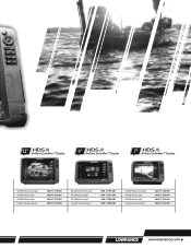
12" Brilliant SolarMax™ Display 9" Brilliant SolarMax™ Display 7" Brilliant SolarMax™ Display 83/200 kHz/LSS/Insight 50/200 kHz/Insight 83/200 kHz/Insight Insight, No transducer 000-11798-001 000-11796-001 000-11795-001 000-11794-001 83/200 kHz/LSS/Insight 50/200 kHz/Insight 83/200 kHz/Insight Insight, No transducer 000-11793-001 000-11791-001 000-11790-001 000-11789-001 83/200 kHz/LSS/Insight 50/200 kHz/Insight 83/200 kHz/Insight Insight, No transducer 000-11788-001 000-11786-001 000-11785-001 000-11784-001 www.lowrance.com
12" Brilliant SolarMax™ Display 9" Brilliant SolarMax™ Display 7" Brilliant SolarMax™ Display 83/200 kHz/LSS/Insight 50/200 kHz/Insight 83/200 kHz/Insight Insight, No transducer 000-11798-001 000-11796-001 000-11795-001 000-11794-001 83/200 kHz/LSS/Insight 50/200 kHz/Insight 83/200 kHz/Insight Insight, No transducer 000-11793-001 000-11791-001 000-11790-001 000-11789-001 83/200 kHz/LSS/Insight 50/200 kHz/Insight 83/200 kHz/Insight Insight, No transducer 000-11788-001 000-11786-001 000-11785-001 000-11784-001 www.lowrance.com


