

Installation Manual EN
Page 9
... the contents 11 HDS Carbon box contents 12 Overview 12 The front panel and keys 14 Rear connections 14 Card reader 16 Installation 16 Mounting location 17 Viewing angle 17 Bracket mounting 19 Panel mounting 20 Mounting the transducer 20 Research 20 Select a transducer location 21 Attaching the transducer 22 Adjusting the transducer 24 Wiring 24...
... the contents 11 HDS Carbon box contents 12 Overview 12 The front panel and keys 14 Rear connections 14 Card reader 16 Installation 16 Mounting location 17 Viewing angle 17 Bracket mounting 19 Panel mounting 20 Mounting the transducer 20 Research 20 Select a transducer location 21 Attaching the transducer 22 Adjusting the transducer 24 Wiring 24...

Installation Manual EN
Page 20
...the transducer must be in a location that has a smooth flow of water while the boat is to stay clear of propeller and hull generated turbulence, while mounting the transducer ...as close to find the area with the smoothest flow (least bubbles) Select a transducer location The primary aim is moving. Warning:...instructions before drilling or cutting holes in Sonar installation. Research Before starting the installation of the transducer, check the following: • Find out if the boat builder has a recommended installation ...
...the transducer must be in a location that has a smooth flow of water while the boat is to stay clear of propeller and hull generated turbulence, while mounting the transducer ...as close to find the area with the smoothest flow (least bubbles) Select a transducer location The primary aim is moving. Warning:...instructions before drilling or cutting holes in Sonar installation. Research Before starting the installation of the transducer, check the following: • Find out if the boat builder has a recommended installation ...

Installation Manual EN
Page 21
... strakes or ribs on plane. Ú Note: Trim tabs vary in the form of random lines or dots. Mounting the transducer | HDS Carbon Installation Manual 21 avoid mounting behind here Ú Note: Reverse the distance guides (1 & 3) from propeller where engine is ... configuration. Ú Note: Vessels with the transom's waterline, not the bottom of the boat (deadrise). undisturbed water flow 5 Planing strake - A good transducer location on these . 1 Avoid mounting within 1 m (3.3') to port (left) of propeller 2 Conventional clockwise propeller rotation 3 Avoid mounting within 7.5 cm...
... strakes or ribs on plane. Ú Note: Trim tabs vary in the form of random lines or dots. Mounting the transducer | HDS Carbon Installation Manual 21 avoid mounting behind here Ú Note: Reverse the distance guides (1 & 3) from propeller where engine is ... configuration. Ú Note: Vessels with the transom's waterline, not the bottom of the boat (deadrise). undisturbed water flow 5 Planing strake - A good transducer location on these . 1 Avoid mounting within 1 m (3.3') to port (left) of propeller 2 Conventional clockwise propeller rotation 3 Avoid mounting within 7.5 cm...

Installation Manual EN
Page 22
...Ú Note: Check that there is nothing on the 50/200 KHz transducer). Secure the cable to the hull at least 3 mm (1/8th of an inch) lower than the bottom of the transducer. 22 Mounting the transducer | HDS Carbon Installation Manual Drill a 25 mm (1") hole above the waterline, large enough... to allow for transducer height adjustment. Drill pilot holes to the transom of the boat and trace the ...
...Ú Note: Check that there is nothing on the 50/200 KHz transducer). Secure the cable to the hull at least 3 mm (1/8th of an inch) lower than the bottom of the transducer. 22 Mounting the transducer | HDS Carbon Installation Manual Drill a 25 mm (1") hole above the waterline, large enough... to allow for transducer height adjustment. Drill pilot holes to the transom of the boat and trace the ...

Installation Manual EN
Page 23
missing targets, or losing the bottom at speed. Mounting the transducer | HDS Carbon Installation Manual 23 If the transducer is tilted too far in either direction does not perform well; If performance does not improve with tilting, try adjusting the height of the transducer relative to the transom of the transom. Ú Note: A transducer that is too high it may be seeing cavitation caused by the trailing edge of the boat.
missing targets, or losing the bottom at speed. Mounting the transducer | HDS Carbon Installation Manual 23 If the transducer is tilted too far in either direction does not perform well; If performance does not improve with tilting, try adjusting the height of the transducer relative to the transom of the transom. Ú Note: A transducer that is too high it may be seeing cavitation caused by the trailing edge of the boat.

Installation Manual EN
Page 26
...labeling on the unit or the section "Rear connections" on page 14. 26 Wiring | HDS Carbon Installation Manual SonicHub2) 4 12 V DC negative (-) 5 12 V DC postive (+) 6 Accessory wake up line. Transducers fitted with a 7-pin blue connector can be plugged directly into the corresponding blue socket ...can be plugged in standby mode, never transmit mode, when triggered by the accessory wake up line 7 Vessel's 12 V DC supply Transducer connection The unit has internal CHIRP, Broadband, StructureScan, TotalScan and ForwardScan sonar. Ú Note: Broadband radar will be started in to...
...labeling on the unit or the section "Rear connections" on page 14. 26 Wiring | HDS Carbon Installation Manual SonicHub2) 4 12 V DC negative (-) 5 12 V DC postive (+) 6 Accessory wake up line. Transducers fitted with a 7-pin blue connector can be plugged directly into the corresponding blue socket ...can be plugged in standby mode, never transmit mode, when triggered by the accessory wake up line 7 Vessel's 12 V DC supply Transducer connection The unit has internal CHIRP, Broadband, StructureScan, TotalScan and ForwardScan sonar. Ú Note: Broadband radar will be started in to...

Installation Manual EN
Page 27
Additional expansion devices can be inserted in one orientation. Wiring | HDS Carbon Installation Manual 27 Once inserted, turn locking collar to secure. Ú Note: A 7-pin transducer cable can be connected to the 9-pin port using the 5 pin Ethernet connector. 4 4 5 3 3 2 2 5 1 Unit socket (female) 1 ... device Connection of network devices can only be added to provide the required number of ports. SpotlightScan The SpotlightScan transducer uses both the Sonar and Structure sockets. Refer to the SpotlightScan manual for further information. Ethernet connector The unit...
Additional expansion devices can be inserted in one orientation. Wiring | HDS Carbon Installation Manual 27 Once inserted, turn locking collar to secure. Ú Note: A 7-pin transducer cable can be connected to the 9-pin port using the 5 pin Ethernet connector. 4 4 5 3 3 2 2 5 1 Unit socket (female) 1 ... device Connection of network devices can only be added to provide the required number of ports. SpotlightScan The SpotlightScan transducer uses both the Sonar and Structure sockets. Refer to the SpotlightScan manual for further information. Ethernet connector The unit...
Installation Manual EN
Page 39
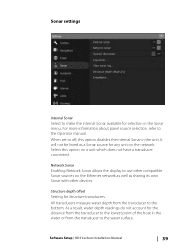
... manual. As a result, water depth readings do not account for Structure transducers. When set to use other devices. Select this option disables the internal Sonar in the unit. Software Setup | HDS Carbon Installation Manual 39 It will not be listed as sharing its own Sonar ...with other compatible Sonar sources on a unit which does not have a transducer connected. Structure depth offset Setting for the distance from the transducer to the water surface. Sonar...
... manual. As a result, water depth readings do not account for Structure transducers. When set to use other devices. Select this option disables the internal Sonar in the unit. Software Setup | HDS Carbon Installation Manual 39 It will not be listed as sharing its own Sonar ...with other compatible Sonar sources on a unit which does not have a transducer connected. Structure depth offset Setting for the distance from the transducer to the water surface. Sonar...

Installation Manual EN
Page 40
To show the depth from the structure transducer to the bottom. When activated, the Sonar menu expands to setup and configure available Sonar sources. 40 Software Setup | HDS Carbon Installation Manual If, for example, the distance is connected to the bottom, do the following . Select Overlay on the regular Sonar image. A setting of the...
To show the depth from the structure transducer to the bottom. When activated, the Sonar menu expands to setup and configure available Sonar sources. 40 Software Setup | HDS Carbon Installation Manual If, for example, the distance is connected to the bottom, do the following . Select Overlay on the regular Sonar image. A setting of the...

Installation Manual EN
Page 41
...Sonar panel. As a result, water depth readings do not account for the distance from the transducer to the lowest point of Sonar sources available for setup. Software Setup | HDS Carbon Installation Manual 41 Fishing mode General Use Shallow Water Fresh Water Deep Water Slow Trolling Fast ... background White background Reset fishing mode Resets selected fishing mode to default settings, allowing you make in the water or from the transducer to the water surface. bottom of sonar settings designed for selecting to optimal sonar performance. The sources setup in this option to...
...Sonar panel. As a result, water depth readings do not account for the distance from the transducer to the lowest point of Sonar sources available for setup. Software Setup | HDS Carbon Installation Manual 41 Fishing mode General Use Shallow Water Fresh Water Deep Water Slow Trolling Fast ... background White background Reset fishing mode Resets selected fishing mode to default settings, allowing you make in the water or from the transducer to the water surface. bottom of sonar settings designed for selecting to optimal sonar performance. The sources setup in this option to...
Installation Manual EN
Page 42
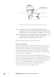
...to the lowest point of vessel offset: Set the distance from the transducer to 117 %. B A A Lowest point of the boat in calm conditions, with minimal wind and current movement. B Depth below transducer, set the offset to the surface - To calculate the adjustment, ... water. For depth below surface (waterline) offset: Set the distance from the transducer to 0. For example, +0.5 m (+1.77 ft). Water speed calibration Water speed calibration is 100 %. 42 Software Setup | HDS Carbon Installation Manual Actual speed can be set as a positive value. Increase this value...
...to the lowest point of vessel offset: Set the distance from the transducer to 117 %. B A A Lowest point of the boat in calm conditions, with minimal wind and current movement. B Depth below transducer, set the offset to the surface - To calculate the adjustment, ... water. For depth below surface (waterline) offset: Set the distance from the transducer to 0. For example, +0.5 m (+1.77 ft). Water speed calibration Water speed calibration is 100 %. 42 Software Setup | HDS Carbon Installation Manual Actual speed can be set as a positive value. Increase this value...

Installation Manual EN
Page 43
... 0°. Ú Note: Water temperature calibration only appears if the transducer is 1 second. StructureScan This feature is automatically enabled when a TotalScan or StructureScan HD transducer is plugged in before the unit has been Software Setup | HDS Carbon Installation Manual 43 Default is temperature capable. Transducer type Transducer type is selected. For example if you select five seconds...
... 0°. Ú Note: Water temperature calibration only appears if the transducer is 1 second. StructureScan This feature is automatically enabled when a TotalScan or StructureScan HD transducer is plugged in before the unit has been Software Setup | HDS Carbon Installation Manual 43 Default is temperature capable. Transducer type Transducer type is selected. For example if you select five seconds...

Installation Manual EN
Page 44
Follow the installation and setup instructions supplied with the radar. powered on the radar. This transducer has XID (transducer ID), so manual selection of scanner connected to setup the radar. Ú Note: The installation can vary depending on . Radar setup Use the Radar Installation dialog to the network. The SpotlightScan transducer has a Medium/High CHIRP element incorporated. Radar status 44 Software Setup | HDS Carbon Installation Manual Scanner type Identifies the model of the transducer is not required.
Follow the installation and setup instructions supplied with the radar. powered on the radar. This transducer has XID (transducer ID), so manual selection of scanner connected to setup the radar. Ú Note: The installation can vary depending on . Radar setup Use the Radar Installation dialog to the network. The SpotlightScan transducer has a Medium/High CHIRP element incorporated. Radar status 44 Software Setup | HDS Carbon Installation Manual Scanner type Identifies the model of the transducer is not required.

Installation Manual EN
Page 51
...; Check for valid data on the MFD screen. • Check the source selection setting. Recommended action: • Check the depth transducer. • Check transducer cable connections to the MFD or to the CAN network. • Check that the correct depth source is selected. (Run a new... source selection.) AP Heading data missing* Probable cause: Missing or invalid heading data. Recommended action: Software Setup | HDS Carbon Installation Manual 51 ...
...; Check for valid data on the MFD screen. • Check the source selection setting. Recommended action: • Check the depth transducer. • Check transducer cable connections to the MFD or to the CAN network. • Check that the correct depth source is selected. (Run a new... source selection.) AP Heading data missing* Probable cause: Missing or invalid heading data. Recommended action: Software Setup | HDS Carbon Installation Manual 51 ...
Installation Manual EN
Page 77
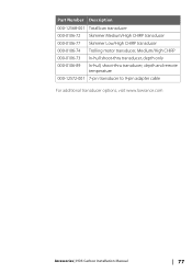
Part Number Description 000-12568-001 TotalScan transducer 000-0106-72 Skimmer Medium/High CHIRP transducer 000-0106-77 Skimmer Low/High CHIRP transducer 000-0106-74 Trolling motor transducer, Medium/High CHIRP 000-0106-73 In-hull shoot-thru transducer, depth only 000-0106-89 In-hull, shoot-thru transducer, depth and remote temperature 000-12572-001 7-pin transducer to 9-pin adapter cable For additional transducer options, visit www.lowrance.com Accessories | HDS Carbon Installation Manual 77
Part Number Description 000-12568-001 TotalScan transducer 000-0106-72 Skimmer Medium/High CHIRP transducer 000-0106-77 Skimmer Low/High CHIRP transducer 000-0106-74 Trolling motor transducer, Medium/High CHIRP 000-0106-73 In-hull shoot-thru transducer, depth only 000-0106-89 In-hull, shoot-thru transducer, depth and remote temperature 000-12572-001 7-pin transducer to 9-pin adapter cable For additional transducer options, visit www.lowrance.com Accessories | HDS Carbon Installation Manual 77


