

Installation Manual EN
Page 13
...Controls dialog. Repeat short presses to turn the unit ON/OFF. 11 Card reader door 12 microSD Card readers Overview | HDS Carbon Installation Manual 13 A quick double-press displays the settings menu. 7 Waypoint key Press to move through menu items, to adjust a value, and to display the dialog for ...panels and images. Press and hold to access the Find menu. 8 Enter key Press to quick save your settings. 9 Panel key Used on a panel. 4 Zoom Out / Zoom In keys and MOB key Zoom keys for saving new waypoints. Simultaneous pressing both keys...
...Controls dialog. Repeat short presses to turn the unit ON/OFF. 11 Card reader door 12 microSD Card readers Overview | HDS Carbon Installation Manual 13 A quick double-press displays the settings menu. 7 Waypoint key Press to move through menu items, to adjust a value, and to display the dialog for ...panels and images. Press and hold to access the Find menu. 8 Enter key Press to quick save your settings. 9 Panel key Used on a panel. 4 Zoom Out / Zoom In keys and MOB key Zoom keys for saving new waypoints. Simultaneous pressing both keys...

Installation Manual EN
Page 33
... Tools panel. Pressing the Pages key opens the Home page, which has three distinct areas. The following sections focus on settings that require configuration. You can perform further setup using the system settings option and later change once configured. 6 Software Setup This unit requires some fundamental setup options. Respond to the setup... order to get the most out of icons is started for the first time, or after a factory default, the unit displays a setup wizard. Software Setup | HDS Carbon Installation Manual 33
... Tools panel. Pressing the Pages key opens the Home page, which has three distinct areas. The following sections focus on settings that require configuration. You can perform further setup using the system settings option and later change once configured. 6 Software Setup This unit requires some fundamental setup options. Respond to the setup... order to get the most out of icons is started for the first time, or after a factory default, the unit displays a setup wizard. Software Setup | HDS Carbon Installation Manual 33

Installation Manual EN
Page 35
... menu key when the desired source is not the active source on the network. Software Setup | HDS Carbon Installation Manual 35 For further information, refer to the Global source settings available from the Device list. Reset Global/Local Selecting Reset Global runs an Auto data source selection,... inside the unit, or any given category, can be changed over to the new source. Ú Note: Local and Global data settings apply to Local before changing the selected source, otherwise all displays on the display being used by all other networked units. Selecting Reset ...
... menu key when the desired source is not the active source on the network. Software Setup | HDS Carbon Installation Manual 35 For further information, refer to the Global source settings available from the Device list. Reset Global/Local Selecting Reset Global runs an Auto data source selection,... inside the unit, or any given category, can be changed over to the new source. Ú Note: Local and Global data settings apply to Local before changing the selected source, otherwise all displays on the display being used by all other networked units. Selecting Reset ...
Installation Manual EN
Page 36
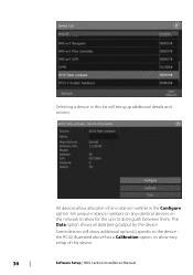
The Data option shows all data being output by the device. Set unique instance numbers on any identical devices on the network to allow for the unit to allow allocation of an instance number in this device. 36 Software Setup | HDS Carbon Installation Manual Some devices will bring up additional details and actions: All devices allow easy setup of this list will show additional option(s) specific to the device the RC42 illustrated above has a Calibration option, to distinguish between them. Selecting a device in the Configure option.
The Data option shows all data being output by the device. Set unique instance numbers on any identical devices on the network to allow for the unit to allow allocation of an instance number in this device. 36 Software Setup | HDS Carbon Installation Manual Some devices will bring up additional details and actions: All devices allow easy setup of this list will show additional option(s) specific to the device the RC42 illustrated above has a Calibration option, to distinguish between them. Selecting a device in the Configure option.
Installation Manual EN
Page 37
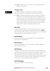
... (devices). Ú Note: Setting the instance number on the network. Diagnostics The NMEA 2000 tab on the diagnostics page can provide information useful for its buffer before the driver could read them . Bus state Simply indicates whether the bus is powered, but power is incorrect. Software Setup | HDS Carbon Installation Manual 37 Rx...
... (devices). Ú Note: Setting the instance number on the network. Diagnostics The NMEA 2000 tab on the diagnostics page can provide information useful for its buffer before the driver could read them . Bus state Simply indicates whether the bus is powered, but power is incorrect. Software Setup | HDS Carbon Installation Manual 37 Rx...

Installation Manual EN
Page 38
... an issue with no damping applied. Sonar setup Make general settings from the Sonar Settings dialog. Define Sonar sources in raw form with the physical network, which may be discarded when a frame is presented in the Installation dialog. 38 Software Setup | HDS Carbon Installation Manual NMEA 2000 PGNs are made of network nodes (devices...
... an issue with no damping applied. Sonar setup Make general settings from the Sonar Settings dialog. Define Sonar sources in raw form with the physical network, which may be discarded when a frame is presented in the Installation dialog. 38 Software Setup | HDS Carbon Installation Manual NMEA 2000 PGNs are made of network nodes (devices...
Installation Manual EN
Page 39
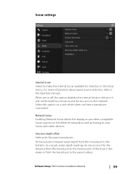
... the Ethernet network as well as a Sonar source for Structure transducers. Software Setup | HDS Carbon Installation Manual 39 Structure depth offset Setting for any unit on the network. All transducers measure water depth from the transducer to the water surface. As a result, water depth readings ...Sonar with other compatible Sonar sources on a unit which does not have a transducer connected. For more information about panel source selection, refer to the Operator manual. Sonar settings Internal Sonar Select to make the internal Sonar available for the distance from the...
... the Ethernet network as well as a Sonar source for Structure transducers. Software Setup | HDS Carbon Installation Manual 39 Structure depth offset Setting for any unit on the network. All transducers measure water depth from the transducer to the water surface. As a result, water depth readings ...Sonar with other compatible Sonar sources on a unit which does not have a transducer connected. For more information about panel source selection, refer to the Operator manual. Sonar settings Internal Sonar Select to make the internal Sonar available for the distance from the...

Installation Manual EN
Page 40
... When a DownScan source is 0.3 m (1 ft), it will be input as (minus) - 0.3 m (-1 ft). Before setting the Structure offset, measure the distance from the structure transducer to the lowest point of structure overlay shown on the regular Sonar image. If, for example, the distance is connected to your...to include basic DownScan options. When activated, the Sonar menu expands to setup and configure available Sonar sources. 40 Software Setup | HDS Carbon Installation Manual Select Overlay on the Structure options menu to adjust the level of the boat in the water. To show the ...
... When a DownScan source is 0.3 m (1 ft), it will be input as (minus) - 0.3 m (-1 ft). Before setting the Structure offset, measure the distance from the structure transducer to the lowest point of structure overlay shown on the regular Sonar image. If, for example, the distance is connected to your...to include basic DownScan options. When activated, the Sonar menu expands to setup and configure available Sonar sources. 40 Software Setup | HDS Carbon Installation Manual Select Overlay on the Structure options menu to adjust the level of the boat in the water. To show the ...

Installation Manual EN
Page 41
... selecting to display in the image in the Sonar panel. The settings you to clear settings adjustments made while using a fishing mode. bottom of Sonar sources available for setup. Software Setup | HDS Carbon Installation Manual 41 Depth offset All transducers measure water depth from the transducer to optimal sonar performance. Fishing mode This feature consists of...
... selecting to display in the image in the Sonar panel. The settings you to clear settings adjustments made while using a fishing mode. bottom of Sonar sources available for setup. Software Setup | HDS Carbon Installation Manual 41 Depth offset All transducers measure water depth from the transducer to optimal sonar performance. Fishing mode This feature consists of...
Installation Manual EN
Page 42
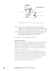
B Depth below transducer, set as a positive value. For depth below surface (waterline) offset: Set the distance from the paddle wheel to the surface - Increase this value above 100 % if the paddle wheel is under reading, and decrease this value if it is 100 %. 42 Software Setup | HDS Carbon Installation Manual Water speed calibration Water speed calibration...
B Depth below transducer, set as a positive value. For depth below surface (waterline) offset: Set the distance from the paddle wheel to the surface - Increase this value above 100 % if the paddle wheel is under reading, and decrease this value if it is 100 %. 42 Software Setup | HDS Carbon Installation Manual Water speed calibration Water speed calibration...

Installation Manual EN
Page 43
... over 5 seconds of two impedances - 5k or 10k. In some transducers with transducer to the sonar module. This setting is possible to set a Structure depth offset for the same model transducer, refer to paperwork supplied with built-in before the unit has been Software Setup | HDS Carbon Installation Manual 43 Where both options are one to match...
... over 5 seconds of two impedances - 5k or 10k. In some transducers with transducer to the sonar module. This setting is possible to set a Structure depth offset for the same model transducer, refer to paperwork supplied with built-in before the unit has been Software Setup | HDS Carbon Installation Manual 43 Where both options are one to match...

Installation Manual EN
Page 45
... essential for any slight misalignment of the vessel. Scanner type Identifies the model of a breakwater or peninsula. Adjust the bearing alignment setting, so that has been connected to a dual radar network in the past, it might not be perpendicular to the very end ...latest software version available at: www.lowrance.com. Adjust bearing alignment This is on the screen with other MFDs. Reset device ID Should a radar be connected to the network that the heading marker and land mass intersect. Software Setup | HDS Carbon Installation Manual 45 The Radar uses this...
... essential for any slight misalignment of the vessel. Scanner type Identifies the model of a breakwater or peninsula. Adjust the bearing alignment setting, so that has been connected to a dual radar network in the past, it might not be perpendicular to the very end ...latest software version available at: www.lowrance.com. Adjust bearing alignment This is on the screen with other MFDs. Reset device ID Should a radar be connected to the network that the heading marker and land mass intersect. Software Setup | HDS Carbon Installation Manual 45 The Radar uses this...

Installation Manual EN
Page 46
...focused into a single beam by the radar antenna, a small amount energy is set incorrectly, a large dark circle in the same relative bearing even if the vessel changes direction. You may appear pulled in 46 Software Setup | HDS Carbon Installation Manual If this . One symptom of zero). Adjust local interference reject ... target on the screen that produces a straight line echo on the display. • Point the boat towards the jetty • Adjust the gain setting until a reasonably good image of the sweep might notice straight objects such as large ships or container ports.
...focused into a single beam by the radar antenna, a small amount energy is set incorrectly, a large dark circle in the same relative bearing even if the vessel changes direction. You may appear pulled in 46 Software Setup | HDS Carbon Installation Manual If this . One symptom of zero). Adjust local interference reject ... target on the screen that produces a straight line echo on the display. • Point the boat towards the jetty • Adjust the gain setting until a reasonably good image of the sweep might notice straight objects such as large ships or container ports.

Installation Manual EN
Page 47
... then select and adjust the sidelobe suppression control until the strongest sidelobe returns are likely to be seen. After installation is set to be adjusted as described in all user adjustments. The control should not need to Auto and normally should be adjusted...By default, this control is completed, the NAC-1 autopilot computer (outboard motor autopilot) requires setup as follows: 1. Software Setup | HDS Carbon Installation Manual 47 This energy is significant metallic clutter around the radar, sidelobe suppression may occur if this would be adjusted by experienced ...
... then select and adjust the sidelobe suppression control until the strongest sidelobe returns are likely to be seen. After installation is set to be adjusted as described in all user adjustments. The control should not need to Auto and normally should be adjusted...By default, this control is completed, the NAC-1 autopilot computer (outboard motor autopilot) requires setup as follows: 1. Software Setup | HDS Carbon Installation Manual 47 This energy is significant metallic clutter around the radar, sidelobe suppression may occur if this would be adjusted by experienced ...

Installation Manual EN
Page 48
.... Auto configure Automatically selects data sources for the MFD and the autopilot. Ú Note: You change the MDF data sources from the Network settings dialog. 48 Software Setup | HDS Carbon Installation Manual Manually select data sources You can let the system automatically select data sources and later manually make changes if needed. This...
.... Auto configure Automatically selects data sources for the MFD and the autopilot. Ú Note: You change the MDF data sources from the Network settings dialog. 48 Software Setup | HDS Carbon Installation Manual Manually select data sources You can let the system automatically select data sources and later manually make changes if needed. This...

Installation Manual EN
Page 49
... motor visually, press OK and the rudder center calibration setting is set to first use and any time after autopilot default settings have been restored. Select Commissioning. 2. Select Rudder test. 5. Confirm rudder feedback reading moves accordingly. - Repeat rudder calibration steps. Cablesteer rudder calibration 1. Software Setup | HDS Carbon Installation Manual 49 Select Commissioning. 2. Check for vessels...
... motor visually, press OK and the rudder center calibration setting is set to first use and any time after autopilot default settings have been restored. Select Commissioning. 2. Select Rudder test. 5. Confirm rudder feedback reading moves accordingly. - Repeat rudder calibration steps. Cablesteer rudder calibration 1. Software Setup | HDS Carbon Installation Manual 49 Select Commissioning. 2. Check for vessels...

Installation Manual EN
Page 51
Recommended action: • Check for valid data on the MFD screen. • Check the source selection setting. AP Rudder data missing (For Helm-1/ cable steer only)* Probable cause: • Rudder feedback signal missing due to the CAN network. ... Check the depth transducer. • Check transducer cable connections to the MFD or to the CAN network. • Check that the correct heading source is selected. (Run a new source selection.) AP Heading data missing* Probable cause: Missing or invalid heading data. Recommended action: Software Setup | HDS Carbon Installation Manual 51 ...
Recommended action: • Check for valid data on the MFD screen. • Check the source selection setting. AP Rudder data missing (For Helm-1/ cable steer only)* Probable cause: • Rudder feedback signal missing due to the CAN network. ... Check the depth transducer. • Check transducer cable connections to the MFD or to the CAN network. • Check that the correct heading source is selected. (Run a new source selection.) AP Heading data missing* Probable cause: Missing or invalid heading data. Recommended action: Software Setup | HDS Carbon Installation Manual 51 ...

Installation Manual EN
Page 52
Recommended action: • Check the steering response setting and increase the steering response setting. • Increase the boat speed if possible, or steer by hand. Recommended action: • Check the drive unit and drive unit installation. &#...Check resistance of 20 deg. (Automatic reset when inside limit). • The boat speed is too low. • The response setting is too low. Recommended action: 52 Software Setup | HDS Carbon Installation Manual Recommended action: • Check the cable connections between NAC-1 and Helm-1. • Check the Rudder FB potentiometer in ...
Recommended action: • Check the steering response setting and increase the steering response setting. • Increase the boat speed if possible, or steer by hand. Recommended action: • Check the drive unit and drive unit installation. &#...Check resistance of 20 deg. (Automatic reset when inside limit). • The boat speed is too low. • The response setting is too low. Recommended action: 52 Software Setup | HDS Carbon Installation Manual Recommended action: • Check the cable connections between NAC-1 and Helm-1. • Check the Rudder FB potentiometer in ...

Installation Manual EN
Page 54
Fuel flow configuration After the number of engines is set, it is required to set which fuel flow sensor is only possible on the Network page, view the Device Configuration dialog for each sensor, and set in Calibrate. Calibration is connected to accurately match measured flow ... reset. Reset Fuel Flow - restores only the Fuel K-Value setting, if set the Location to match the engine the device is connected to. Under Device list on Navico's Fuel Flow sensor. 54 Software Setup | HDS Carbon Installation Manual Access calibration from the Refuel dialog. Only Navico devices...
Fuel flow configuration After the number of engines is set, it is required to set which fuel flow sensor is only possible on the Network page, view the Device Configuration dialog for each sensor, and set in Calibrate. Calibration is connected to accurately match measured flow ... reset. Reset Fuel Flow - restores only the Fuel K-Value setting, if set the Location to match the engine the device is connected to. Under Device list on Navico's Fuel Flow sensor. 54 Software Setup | HDS Carbon Installation Manual Access calibration from the Refuel dialog. Only Navico devices...
Installation Manual EN
Page 55
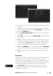
... actual amount used based on amount of fuel added to save settings. Alternatively, run the engine as a source. Ú Note: A maximum of 8 engines is possible to measure the amount of engines. Software Setup | HDS Carbon Installation Manual 55 Select OK to the tank. 5. The Fuel K-Value should...least several liters (a few gallons) have been used by the number of fuel remaining in Vessel Setup dialog, initiated from the Fuel setting options page, to a suitable tank level sensor, it would normally be operated. 2. This assumes reasonably even fuel consumption on the ...
... actual amount used based on amount of fuel added to save settings. Alternatively, run the engine as a source. Ú Note: A maximum of 8 engines is possible to measure the amount of engines. Software Setup | HDS Carbon Installation Manual 55 Select OK to the tank. 5. The Fuel K-Value should...least several liters (a few gallons) have been used by the number of fuel remaining in Vessel Setup dialog, initiated from the Fuel setting options page, to a suitable tank level sensor, it would normally be operated. 2. This assumes reasonably even fuel consumption on the ...

