
SW420 GL BOARD Manual
Page 1
VISIT WWW.LIFTMASTER.COM TO LOCATE A PROFESSIONAL INSTALLING DEALER IN YOUR AREA. MODEL SW420 IS FOR VEHICULAR PASSAGE GATES ONLY AND IS NOT INTENDED FOR PEDESTRIAN PASSAGE GATE USE. GLCONTROLLER BOARD MODEL SW420 LIGHT DUTY SWING GATE OPERATOR 2 YEAR WARRANTY Serial located on electrical box cover) Installation Date INTENDED FOR PROFESSIONAL INSTALLATION ONLY. THIS MANUAL IS TO BE LEFT WITH THE PROPERTY OWNER.
VISIT WWW.LIFTMASTER.COM TO LOCATE A PROFESSIONAL INSTALLING DEALER IN YOUR AREA. MODEL SW420 IS FOR VEHICULAR PASSAGE GATES ONLY AND IS NOT INTENDED FOR PEDESTRIAN PASSAGE GATE USE. GLCONTROLLER BOARD MODEL SW420 LIGHT DUTY SWING GATE OPERATOR 2 YEAR WARRANTY Serial located on electrical box cover) Installation Date INTENDED FOR PROFESSIONAL INSTALLATION ONLY. THIS MANUAL IS TO BE LEFT WITH THE PROPERTY OWNER.
SW420 GL BOARD Manual
Page 2
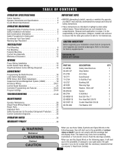
...damage to your installation check that all safety instructions. • These instructions are not intended to be comprehensive. Read them . HARDWARE KIT SW420 (K77-SW420) PART NO. 01-G0582 02-401-SP 07-2705 10-2111 11-2754 12-2727 40-3505 80-10026 80-206-65 80-... 16 Limit Switch Adjustment 17 RPM Sensor (Hall Effect) Adjustment 18 Sequenced Access Management System (SAMS 19 Accessory Wiring 20-21 Control Board Illustration 22 Controller Programming and Features 23-24 Program Settings 25-26 TROUBLESHOOTING 27-28 MAINTENANCE Operator Maintenance 29 Single Phase Wiring Diagram 30...
...damage to your installation check that all safety instructions. • These instructions are not intended to be comprehensive. Read them . HARDWARE KIT SW420 (K77-SW420) PART NO. 01-G0582 02-401-SP 07-2705 10-2111 11-2754 12-2727 40-3505 80-10026 80-206-65 80-... 16 Limit Switch Adjustment 17 RPM Sensor (Hall Effect) Adjustment 18 Sequenced Access Management System (SAMS 19 Accessory Wiring 20-21 Control Board Illustration 22 Controller Programming and Features 23-24 Program Settings 25-26 TROUBLESHOOTING 27-28 MAINTENANCE Operator Maintenance 29 Single Phase Wiring Diagram 30...
SW420 GL BOARD Manual
Page 18
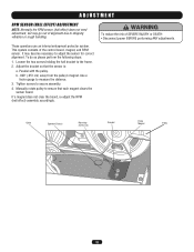
...out of alignment due to shipping vibration or rough handling. Adjust the bracket so that each magnet clears the sensor board. If a magnet does not clear the board, re-adjust the RPM (hall effect) assembly accordingly. Tighten screws to the frame. 2. Manually rotate pulley ...to ensure that the sensor is: a. WARNING To reduce the risk of the control board, magnet, and RPM sensor. AVERT AVERT ATTEN Cable Operator Chassis Mounting Screws (2) Bracket Pulley Magnet AVER Pulley ADVERTENCIA PRECAUCIÓN 18 ADJUSTMENT...
...out of alignment due to shipping vibration or rough handling. Adjust the bracket so that each magnet clears the sensor board. If a magnet does not clear the board, re-adjust the RPM (hall effect) assembly accordingly. Tighten screws to the frame. 2. Manually rotate pulley ...to ensure that the sensor is: a. WARNING To reduce the risk of the control board, magnet, and RPM sensor. AVERT AVERT ATTEN Cable Operator Chassis Mounting Screws (2) Bracket Pulley Magnet AVER Pulley ADVERTENCIA PRECAUCIÓN 18 ADJUSTMENT...
SW420 GL BOARD Manual
Page 19
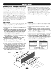
... next vehicle to access the SAMS system will automatically close followed by first opening the gate farthest from terminal J1-5 on the control board to terminal 3 on the auxiliary limit switch. 8. When an authorized vehicle accesses the gate system, the SAM system responds by the...a slower moving more control when managing vehicular entrances to areas such as apartment complexes, businesses and gated communities. Install conduit between the BG770 SW420. 3. If using a device, such as a single or pair of the system is that traffic is closed the slide or swing gate...
... next vehicle to access the SAMS system will automatically close followed by first opening the gate farthest from terminal J1-5 on the control board to terminal 3 on the auxiliary limit switch. 8. When an authorized vehicle accesses the gate system, the SAM system responds by the...a slower moving more control when managing vehicular entrances to areas such as apartment complexes, businesses and gated communities. Install conduit between the BG770 SW420. 3. If using a device, such as a single or pair of the system is that traffic is closed the slide or swing gate...

SW420 GL BOARD Manual
Page 20
... Terminal Blocks R1 R2 R3 R4 3 5 5 8 9 10 11 12 1 2 3 4 5 6 7 8 9 10 11 12 13 14 15 16 J1 Terminal Block FREQ FREQ FREQ 24 Vac Control Board J1 Terminals 1 & 5 - Accessories that you follow the UL guidelines presented throughout the manual. NOTE: Will not override a double entrapment (signalled by activating the remote control...
... Terminal Blocks R1 R2 R3 R4 3 5 5 8 9 10 11 12 1 2 3 4 5 6 7 8 9 10 11 12 13 14 15 16 J1 Terminal Block FREQ FREQ FREQ 24 Vac Control Board J1 Terminals 1 & 5 - Accessories that you follow the UL guidelines presented throughout the manual. NOTE: Will not override a double entrapment (signalled by activating the remote control...
SW420 GL BOARD Manual
Page 22
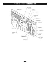
CONTROL BOARD ILLUSTRATION Main Terminal Wiring J4 Connector Master/Second Dip Switch #4 Master/Second Potentiometer Timer-to-Close Potentiometer Force Adjustment Dip Switch #2 Dip Switch #1 Diagnostic LED J2 Connector J5 Connector SAMS Relay Drive Troubleshooting LEDs J1 Terminal Troubleshooting LEDs Limit LEDs Programming Port (factory use only) Motor Learn Button J3 Connector Aux. Relay Drive (not used) 22
CONTROL BOARD ILLUSTRATION Main Terminal Wiring J4 Connector Master/Second Dip Switch #4 Master/Second Potentiometer Timer-to-Close Potentiometer Force Adjustment Dip Switch #2 Dip Switch #1 Diagnostic LED J2 Connector J5 Connector SAMS Relay Drive Troubleshooting LEDs J1 Terminal Troubleshooting LEDs Limit LEDs Programming Port (factory use only) Motor Learn Button J3 Connector Aux. Relay Drive (not used) 22

SW420 GL BOARD Manual
Page 23
... learn button. Press the motor learn the motor: NOTE: Motor Learn must remain attached to flash rapidly. 3. Install a jumper on either board or motor is reached. The yellow LED should start to the gate throughout the entire process. 2. If the unit activates a limit before ... this will go back to differentiate between master and second during run for the open override, close override and stop . ADJUSTMENT CONTROL BOARD PROGRAMMING AND FEATURES MOTOR LEARN FUNCTION (FORCE PROFILE) This function is learned. Switch "S3" is on previous page. The operator must...
... learn button. Press the motor learn the motor: NOTE: Motor Learn must remain attached to flash rapidly. 3. Install a jumper on either board or motor is reached. The yellow LED should start to the gate throughout the entire process. 2. If the unit activates a limit before ... this will go back to differentiate between master and second during run for the open override, close override and stop . ADJUSTMENT CONTROL BOARD PROGRAMMING AND FEATURES MOTOR LEARN FUNCTION (FORCE PROFILE) This function is learned. Switch "S3" is on previous page. The operator must...
SW420 GL BOARD Manual
Page 24
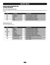
... LEDS There are 5 troubleshooting LEDs on relay drives K1 through K5. These LEDs will be illuminated when the microcontroller relay drive is activated. ADJUSTMENT CONTROL BOARD PROGRAMMING AND FEATURES (CONTINUED) RELAY DRIVE TROUBLESHOOTING LEDS There are 9 troubleshooting LEDs.
... LEDS There are 5 troubleshooting LEDs on relay drives K1 through K5. These LEDs will be illuminated when the microcontroller relay drive is activated. ADJUSTMENT CONTROL BOARD PROGRAMMING AND FEATURES (CONTINUED) RELAY DRIVE TROUBLESHOOTING LEDS There are 9 troubleshooting LEDs.
SW420 GL BOARD Manual
Page 25
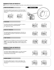
.../LEFT OPERATION This switch selects the gate opening direction, to the left or to -Close feature works in conjunction with the potentiometer located on the board. TIMER-TO-CLOSE ENABLE TIMER-TO-CLOSE This switch enables the auto close timer. When switch is determined from the inside of fence looking out...
.../LEFT OPERATION This switch selects the gate opening direction, to the left or to -Close feature works in conjunction with the potentiometer located on the board. TIMER-TO-CLOSE ENABLE TIMER-TO-CLOSE This switch enables the auto close timer. When switch is determined from the inside of fence looking out...
SW420 GL BOARD Manual
Page 26
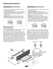
... MAG CLED OPED WARN MAG S2 ON ON 1 2 34 S2 ON ON 1 2 34 PH PH PH PH MASTER/SECOND SYSTEMS Dual Gate Communications The control board is cleared the gate continues to initiate proper Master/Second communication. If the master detects the presence of running the operator in stand alone mode...
... MAG CLED OPED WARN MAG S2 ON ON 1 2 34 S2 ON ON 1 2 34 PH PH PH PH MASTER/SECOND SYSTEMS Dual Gate Communications The control board is cleared the gate continues to initiate proper Master/Second communication. If the master detects the presence of running the operator in stand alone mode...

SW420 GL BOARD Manual
Page 27
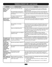
...wiring is installed correctly and is bad, check transformer wiring and replace transformer. Problem in the operator. Make sure there is a control board next to run. Check the green LED (D17) on page 23. Low or no high voltage power. If the high voltage power...this manual. belt/drive chain. An installed accessory may be within 5% of over heating. The voltage at the top right of the control board. Examine the motor's labels for the distance between the two units is a jumper installed across terminals J1-3 & J1-5 of the communication failure...
...wiring is installed correctly and is bad, check transformer wiring and replace transformer. Problem in the operator. Make sure there is a control board next to run. Check the green LED (D17) on page 23. Low or no high voltage power. If the high voltage power...this manual. belt/drive chain. An installed accessory may be within 5% of over heating. The voltage at the top right of the control board. Examine the motor's labels for the distance between the two units is a jumper installed across terminals J1-3 & J1-5 of the communication failure...
SW420 GL BOARD Manual
Page 28
... and swing the gate open limit. Remove the accessory and test the operator. Programming changes do so will Radio terminals R1-4 are on the control board. If the switch S1-1 is adjusted correctly but then stops and reverses direction. Open photo eye reverses gate closed when activated during opening. Refer to...
... and swing the gate open limit. Remove the accessory and test the operator. Programming changes do so will Radio terminals R1-4 are on the control board. If the switch S1-1 is adjusted correctly but then stops and reverses direction. Open photo eye reverses gate closed when activated during opening. Refer to...

SW420 GL BOARD Manual
Page 30
GL FIELD WIRING & ADJUSTMENTS MODEL TYPES: HORSEPOWER: VOLTAGE/PHASE: SW420 1/3 115V & 230V - 1 PHASE ONLY 845 Larch Avenue, Elmhurst, IL 60125 G1977 DRAWING NUMBER: 30 REV: C CLOSE 24 VAC-COMMON DC-GND LOCK 1 LOCK 1 ALARM 1 ... TERMINAL DESIGNATIONS SHOWN FOR 115V ONLY. 3) OPTIONAL WIRE HARNESS. 4) (B+) AND (B-) ARE 100dB SAFETY ALARMS. 5) CONNECTED INTERNALLY ON GL PC BOARD APPLICATIONS: CONTROL WIRING TYPE - OPEN OBS. SINGLE PHASE WIRING DIAGRAM GL CONTROL BOARD 24VAC-IN 24VAC-COMMON SOFT OPEN NC "B" LIMIT CONTACTOR B "A" LIMIT CONTACTOR A RPM-IN RPM-SUPPLY RPM GND RADIO COMMAND...
GL FIELD WIRING & ADJUSTMENTS MODEL TYPES: HORSEPOWER: VOLTAGE/PHASE: SW420 1/3 115V & 230V - 1 PHASE ONLY 845 Larch Avenue, Elmhurst, IL 60125 G1977 DRAWING NUMBER: 30 REV: C CLOSE 24 VAC-COMMON DC-GND LOCK 1 LOCK 1 ALARM 1 ... TERMINAL DESIGNATIONS SHOWN FOR 115V ONLY. 3) OPTIONAL WIRE HARNESS. 4) (B+) AND (B-) ARE 100dB SAFETY ALARMS. 5) CONNECTED INTERNALLY ON GL PC BOARD APPLICATIONS: CONTROL WIRING TYPE - OPEN OBS. SINGLE PHASE WIRING DIAGRAM GL CONTROL BOARD 24VAC-IN 24VAC-COMMON SOFT OPEN NC "B" LIMIT CONTACTOR B "A" LIMIT CONTACTOR A RPM-IN RPM-SUPPLY RPM GND RADIO COMMAND...

SW420 GL BOARD Manual
Page 31
... 1 Roll Pin 2 Belt 1 Molded Pulley 1 Spacer 1 Washer 7 Phillips Screw 10-32x2-1/2" 1 31 Refer to page 36 for 230V 1 Terminal Strip 1 Control Board, GL 1 Hinge Bracket 2 Control Box 1 Tie Wrap 14" 2 Aluminum Standoff 1 Nylon Standoff 2 Terminal Strip Insulator 2 Tinnerman Nut 5 Plastic Card Guide 6" 1...REPAIR PARTS Refer to the parts lists below for replacement parts available for your motor and remove the second dash (-). For example: SW420-33-11 (Operator) = K73SW420-33-11 (Electrical Box Kit) Motor Kits To order a motor replacement kit, add a K ...
... 1 Roll Pin 2 Belt 1 Molded Pulley 1 Spacer 1 Washer 7 Phillips Screw 10-32x2-1/2" 1 31 Refer to page 36 for 230V 1 Terminal Strip 1 Control Board, GL 1 Hinge Bracket 2 Control Box 1 Tie Wrap 14" 2 Aluminum Standoff 1 Nylon Standoff 2 Terminal Strip Insulator 2 Tinnerman Nut 5 Plastic Card Guide 6" 1...REPAIR PARTS Refer to the parts lists below for replacement parts available for your motor and remove the second dash (-). For example: SW420-33-11 (Operator) = K73SW420-33-11 (Electrical Box Kit) Motor Kits To order a motor replacement kit, add a K ...
SW420 GL BOARD Manual
Page 34
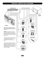
...6 7 8 9 10 11 12 13 14 15 16 Field Wiring Terminal Blocks R1 R2 R3 R4 3 5 5 8 9 10 11 12 24 Vac GL Board NOTE: SEE WIRING DIAGRAMS SHIPPED WITH KIT FOR ADDITIONAL INFORMATION. If these instructions are contrary to operate the gate system, MUST be installed where the... LOOP INPUT (N.O.) OBSTRUCTION OPEN EDGE/PHOTO EYE INPUT (N.O.) OBSTRUCTION CLOSE EDGE/PHOTO EYE INPUT (N.O.) RESIDENTIAL RADIO (SINGLE BUTTON) INPUT (N.O.) SW420 Operator 34 SEE OWNERS MANUAL FOR WIRING DISTANCES AND WIRE GAUGE INFORMATION. WARNING: All controls that you follow the instructions provided by the ...
...6 7 8 9 10 11 12 13 14 15 16 Field Wiring Terminal Blocks R1 R2 R3 R4 3 5 5 8 9 10 11 12 24 Vac GL Board NOTE: SEE WIRING DIAGRAMS SHIPPED WITH KIT FOR ADDITIONAL INFORMATION. If these instructions are contrary to operate the gate system, MUST be installed where the... LOOP INPUT (N.O.) OBSTRUCTION OPEN EDGE/PHOTO EYE INPUT (N.O.) OBSTRUCTION CLOSE EDGE/PHOTO EYE INPUT (N.O.) RESIDENTIAL RADIO (SINGLE BUTTON) INPUT (N.O.) SW420 Operator 34 SEE OWNERS MANUAL FOR WIRING DISTANCES AND WIRE GAUGE INFORMATION. WARNING: All controls that you follow the instructions provided by the ...

SW420 S3 BOARD Manual
Page 18
... the inherent obstruction described above. TIME DELAY TO REVERSE CIRCUIT Allows the gate to come to reverse. DIGITAL MICROPROCESSOR This is the main circuit board for the system. Obstruction Sensing INHERENT OBSTRUCTION PROTECTION The pulley is defeated when either function as a single button or to function as opening or... such as a pushbutton within site of R.P.Ms. will not activate from any automatic system, including the built in a similar manner to this circuit board. 18 System Features CLOSE SINGLE BUTTON SELECT The single button (programmable) control can be used .
... the inherent obstruction described above. TIME DELAY TO REVERSE CIRCUIT Allows the gate to come to reverse. DIGITAL MICROPROCESSOR This is the main circuit board for the system. Obstruction Sensing INHERENT OBSTRUCTION PROTECTION The pulley is defeated when either function as a single button or to function as opening or... such as a pushbutton within site of R.P.Ms. will not activate from any automatic system, including the built in a similar manner to this circuit board. 18 System Features CLOSE SINGLE BUTTON SELECT The single button (programmable) control can be used .
SW420 S3 BOARD Manual
Page 19
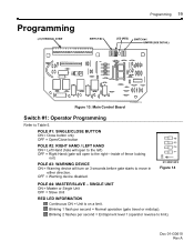
... INFORMATION Continuous ON = Unit is on 3 seconds before gate starts to Table 5. Doc 01-G0610 Rev A Programming Programming 19 01-G0610F13 Figure 13: Main Control Board Switch #1: Operator Programming Refer to move in either direction. OFF = Warning device disabled. Blinking 1 flash per second = Entrapment level 1 (operator reverse to limit...
... INFORMATION Continuous ON = Unit is on 3 seconds before gate starts to Table 5. Doc 01-G0610 Rev A Programming Programming 19 01-G0610F13 Figure 13: Main Control Board Switch #1: Operator Programming Refer to move in either direction. OFF = Warning device disabled. Blinking 1 flash per second = Entrapment level 1 (operator reverse to limit...
SW420 S3 BOARD Manual
Page 24
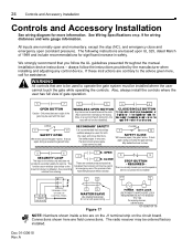
... must sense people. CLOSE These are based upon UL 325, dated March of 1999 and include recommendations for assistance. See Wiring Specifications on the circuit board. REQUIRED - 24 Controls and Accessory Installation Controls and Accessory Installation See wiring diagram for wiring distances and wire gauge information. WARNING All controls that bypasses...
... must sense people. CLOSE These are based upon UL 325, dated March of 1999 and include recommendations for assistance. See Wiring Specifications on the circuit board. REQUIRED - 24 Controls and Accessory Installation Controls and Accessory Installation See wiring diagram for wiring distances and wire gauge information. WARNING All controls that bypasses...
SW420 S3 BOARD Manual
Page 29
... into the motor itself, while other units have a bad power disconnect and it look like there is recommended that should be checked at the circuit board at either the full open or full close as possible to shut off at terminals J1-3 & J1-11. 4C. There are S.P.D.T. (single pole, double ...or wheel. Doc 01-G0610 Rev A The only thing that it at the transformer primary terminals. It is thought to J1-3 and J1-5. The circuit board is the "brains" of the different programs and their functions can be checked is close position. 4D. If there is voltage at the switch and...
... into the motor itself, while other units have a bad power disconnect and it look like there is recommended that should be checked at the circuit board at either the full open or full close as possible to shut off at terminals J1-3 & J1-11. 4C. There are S.P.D.T. (single pole, double ...or wheel. Doc 01-G0610 Rev A The only thing that it at the transformer primary terminals. It is thought to J1-3 and J1-5. The circuit board is the "brains" of the different programs and their functions can be checked is close position. 4D. If there is voltage at the switch and...

SW420 S3 BOARD Manual
Page 32
...3/8 x .010 SHIM (N) 1-1/2 x 1.03 x .015 SPACER 1 x 1/16 WASHER .656 x 1-1/4 x .06 SPACER (N) 3/16 x 1 KEY (N) 1/4 x 1/4 x 1 KEY (N) STANDOFF FOR FAIL SAFE BOARD (OPTIONAL) NEOPRENE O-RING (N) 1/4 x 1/4 x 3/4 KEY (N) 5/8 x 1-1/4 CLEVIS PIN HUB LATCH PIN U-BOLT NUT TOOL 3/16 x 3/4 SQUARE KEY (N) 6" PLASTIC CARD GUIDE 5/16-18 x 3/8 BUTTON HEAD ... (N) 6-32 x 3/8 SELF TAPPING SCREW 6-32 x 1/2 PHILLIP PAN HEAD SCREW (N) 6-32 x 2-1/2 SLOTTED ROUND HEAD SCREW (N) 8-32 x 1/4 SELF TAPPING PHIL. SW420 Part # 02-041-SP 07-2703 07-2704 07-2705 07-2706 10-2111 10-2701-T 10-2702 10-2703 10-2704 10-2705-T 10...
...3/8 x .010 SHIM (N) 1-1/2 x 1.03 x .015 SPACER 1 x 1/16 WASHER .656 x 1-1/4 x .06 SPACER (N) 3/16 x 1 KEY (N) 1/4 x 1/4 x 1 KEY (N) STANDOFF FOR FAIL SAFE BOARD (OPTIONAL) NEOPRENE O-RING (N) 1/4 x 1/4 x 3/4 KEY (N) 5/8 x 1-1/4 CLEVIS PIN HUB LATCH PIN U-BOLT NUT TOOL 3/16 x 3/4 SQUARE KEY (N) 6" PLASTIC CARD GUIDE 5/16-18 x 3/8 BUTTON HEAD ... (N) 6-32 x 3/8 SELF TAPPING SCREW 6-32 x 1/2 PHILLIP PAN HEAD SCREW (N) 6-32 x 2-1/2 SLOTTED ROUND HEAD SCREW (N) 8-32 x 1/4 SELF TAPPING PHIL. SW420 Part # 02-041-SP 07-2703 07-2704 07-2705 07-2706 10-2111 10-2701-T 10-2702 10-2703 10-2704 10-2705-T 10...


