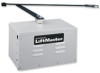
SW420 GL BOARD Manual
Page 2
...designer, installer and end user to ensure that all safety instructions. • These instructions are not intended to be comprehensive. HARDWARE KIT SW420 (K77-SW420) PART NO. 01-G0582 02-401-SP 07-2705 10-2111 11-2754 12-2727 40-3505 80-10026 80-206-65 80-... Switch Power Wiring 15 Stop/Reset Button Control Wiring (Required 15 ADJUSTMENT Programming the Radio Receiver 16 Limit Switch Adjustment 17 RPM Sensor (Hall Effect) Adjustment 18 Sequenced Access Management System (SAMS 19 Accessory Wiring 20-21 Control Board Illustration 22 Controller Programming and Features 23-24 Program...
...designer, installer and end user to ensure that all safety instructions. • These instructions are not intended to be comprehensive. HARDWARE KIT SW420 (K77-SW420) PART NO. 01-G0582 02-401-SP 07-2705 10-2111 11-2754 12-2727 40-3505 80-10026 80-206-65 80-... Switch Power Wiring 15 Stop/Reset Button Control Wiring (Required 15 ADJUSTMENT Programming the Radio Receiver 16 Limit Switch Adjustment 17 RPM Sensor (Hall Effect) Adjustment 18 Sequenced Access Management System (SAMS 19 Accessory Wiring 20-21 Control Board Illustration 22 Controller Programming and Features 23-24 Program...
SW420 GL BOARD Manual
Page 18
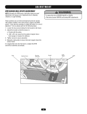
ADJUSTMENT RPM SENSOR (HALL EFFECT) ADJUSTMENT NOTE: Normally the RPM sensor (hall effect) does not need adjustment, but may become necessary to adjust the sensor for correct alignment. These operators use an internal entrapment protector system. b. .... to secure assembly. 4. If a magnet does not clear the board, re-adjust the RPM (hall effect) assembly accordingly. Parallel with the pulley. Tighten screws to measure the distance. 3. Loosen the two screws holding the hall bracket to shipping vibration or rough handling. To do so please perform the following steps: 1. WARNING...
ADJUSTMENT RPM SENSOR (HALL EFFECT) ADJUSTMENT NOTE: Normally the RPM sensor (hall effect) does not need adjustment, but may become necessary to adjust the sensor for correct alignment. These operators use an internal entrapment protector system. b. .... to secure assembly. 4. If a magnet does not clear the board, re-adjust the RPM (hall effect) assembly accordingly. Parallel with the pulley. Tighten screws to measure the distance. 3. Loosen the two screws holding the hall bracket to shipping vibration or rough handling. To do so please perform the following steps: 1. WARNING...

SW420 GL BOARD Manual
Page 23
... LED (DIAG) is learned. LED Code Flashed Diagnostic Meaning Cleared By OFF 1 2 3 4 5 6 On No Flash Normal operation Single entrapment sensed Double entrapment Failed or no hall effect sensor Exceed maximum motor run time Limit fault Loss of communications between the different diagnostic codes. Failure to flash rapidly. 3. If the LED goes out...
... LED (DIAG) is learned. LED Code Flashed Diagnostic Meaning Cleared By OFF 1 2 3 4 5 6 On No Flash Normal operation Single entrapment sensed Double entrapment Failed or no hall effect sensor Exceed maximum motor run time Limit fault Loss of communications between the different diagnostic codes. Failure to flash rapidly. 3. If the LED goes out...
SW420 GL BOARD Manual
Page 28
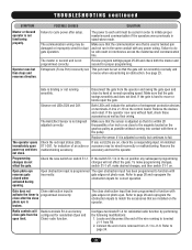
...the control board. Failure to J1-6. The operator opens immediately upon power up and does not close gate from J1-1 to do not effect the gate. Remove the accessory and test the operator. Refer to move or binds repair the gate. Connect the end of wire removed... or improperly wired for residential radio function by hand at normal operating speed. If the gate is not aligned/ adjusted correctly. The Hall Effect Sensor is hard to page 26 and reprogram the obstruction inputs for proper programming. Gate does not Close obstruction input is not programmed correctly...
...the control board. Failure to J1-6. The operator opens immediately upon power up and does not close gate from J1-1 to do not effect the gate. Remove the accessory and test the operator. Refer to move or binds repair the gate. Connect the end of wire removed... or improperly wired for residential radio function by hand at normal operating speed. If the gate is not aligned/ adjusted correctly. The Hall Effect Sensor is hard to page 26 and reprogram the obstruction inputs for proper programming. Gate does not Close obstruction input is not programmed correctly...
SW420 GL BOARD Manual
Page 29
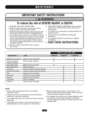
...anytime a malfunction is suggested that the incoming voltage to gate hardware. 7. Inspection and service should always be performed by a LiftMaster professional. 10. Limit switches may have to adjust AVERTISSEMENT and retest the gate operator properly can increase the risk of INJURY or...to the operator it is NOT moving. AVERTISSEMENT DESCRIPTION TASK CHECK AT LEAST ONCE EVERY 3 MONTHS 6 MONTHS 12 MONTHS RPM Sensor (Hall Effect) Check for proper adjustment X X External Entrapment Check for proper operation X X Protection Systems Gate Caution Signs Make sure they are ...
...anytime a malfunction is suggested that the incoming voltage to gate hardware. 7. Inspection and service should always be performed by a LiftMaster professional. 10. Limit switches may have to adjust AVERTISSEMENT and retest the gate operator properly can increase the risk of INJURY or...to the operator it is NOT moving. AVERTISSEMENT DESCRIPTION TASK CHECK AT LEAST ONCE EVERY 3 MONTHS 6 MONTHS 12 MONTHS RPM Sensor (Hall Effect) Check for proper adjustment X X External Entrapment Check for proper operation X X Protection Systems Gate Caution Signs Make sure they are ...

SW420 GL BOARD Manual
Page 31
.... prefix to the number of individual components. For example: SW420-33-11 (Operator) = K73SW420-33-11 (Electrical Box Kit) Motor Kits To order a motor replacement kit, add a K prefix to the model number of each kit may be available. SPST 2 Reducer 30:1 1 Limit Collar 1 Hall Effect Assembly 1 Roll Pin 2 Belt 1 Molded Pulley 1 Spacer 1 Washer...
.... prefix to the number of individual components. For example: SW420-33-11 (Operator) = K73SW420-33-11 (Electrical Box Kit) Motor Kits To order a motor replacement kit, add a K prefix to the model number of each kit may be available. SPST 2 Reducer 30:1 1 Limit Collar 1 Hall Effect Assembly 1 Roll Pin 2 Belt 1 Molded Pulley 1 Spacer 1 Washer...

SW420 S3 BOARD Manual
Page 32
... #8 EXTERNAL TOOTH WASHER (N) Qty. 5 2 1 6 4 1 1 4 1 1 1 1 2 1 1 2 2 2 3 1 2 4 24 3 1 3 2 2 3 4 2 1 1 2 4 1 1 2 2 2 2 5 4 2 3 4 1 1 1 2 7 2 1 1 2 1 1 1 1 2 1 1 3 3 1 Table 8: Parts List Doc 01-G0610 Rev A SW420 Part # 02-041-SP 07-2703 07-2704 07-2705 07-2706 10-2111 10-2701-T 10-2702 10-2703 10-2704 10-2705-T 10...(N) 3/4" SHORTY BUSHING (N) CONDUIT BOX 4 x 4 x 2.125 DEEP 2 OHM RESISTOR w/MTG BRACKET HALL EFFECT BOARD (N) 70MFD 220V CAPACITOR ALARM HIGH OUTPUT W/DIODE (N) HALL EFFECT SENSOR (N) NYLON SENSOR SPACER (N) ALUMINUM HEX STANDOFF NYLON HEX STANDOFF 30:1 REDUCER S3 ALARM SPACER (N) ...
... #8 EXTERNAL TOOTH WASHER (N) Qty. 5 2 1 6 4 1 1 4 1 1 1 1 2 1 1 2 2 2 3 1 2 4 24 3 1 3 2 2 3 4 2 1 1 2 4 1 1 2 2 2 2 5 4 2 3 4 1 1 1 2 7 2 1 1 2 1 1 1 1 2 1 1 3 3 1 Table 8: Parts List Doc 01-G0610 Rev A SW420 Part # 02-041-SP 07-2703 07-2704 07-2705 07-2706 10-2111 10-2701-T 10-2702 10-2703 10-2704 10-2705-T 10...(N) 3/4" SHORTY BUSHING (N) CONDUIT BOX 4 x 4 x 2.125 DEEP 2 OHM RESISTOR w/MTG BRACKET HALL EFFECT BOARD (N) 70MFD 220V CAPACITOR ALARM HIGH OUTPUT W/DIODE (N) HALL EFFECT SENSOR (N) NYLON SENSOR SPACER (N) ALUMINUM HEX STANDOFF NYLON HEX STANDOFF 30:1 REDUCER S3 ALARM SPACER (N) ...


