
SL930 Addendum Manual
Page 1
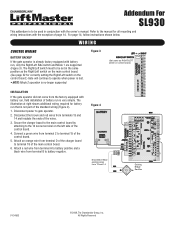
... 3. Connect a green wire from terminals 13 and 14 and insulate the ends of the control board. 5. All Rights Reserved Refer to the manual for battery run that is not part of battery run is very simple. The Right/Left switch must to be used in the same position...to battery positive and a black wire from 13 and 14. For page 14, follow instructions shown below. Addendum For SL930 This addendum is to be set in conjunction with the owner's manual. Existing Bridge Rectifier 01-34563 © 2008, The Chamberlain Group, Inc. The illustration at right shows additional wiring...
... 3. Connect a green wire from terminals 13 and 14 and insulate the ends of the control board. 5. All Rights Reserved Refer to the manual for battery run that is not part of battery run is very simple. The Right/Left switch must to be used in the same position...to battery positive and a black wire from 13 and 14. For page 14, follow instructions shown below. Addendum For SL930 This addendum is to be set in conjunction with the owner's manual. Existing Bridge Rectifier 01-34563 © 2008, The Chamberlain Group, Inc. The illustration at right shows additional wiring...
SL930 Manual
Page 2
...ATTENTION were provided and received undamaged. OPERATION AND MAINTENANCE 25 TROUBLESHOOTING Visual Feedback LEDs 26 SL930 Troubleshooting 27-28 • OPERATOR • OWNER'S MANUAL • HARDWARE KIT SL930 (K77-40335) Complete with the warnings that accompany it will alert you to the ..., operate or maintain the operator, you MUST read and fully understand this Signal Word on the following pages, it . Model SL930 30 Illustrated Parts - The hazard may come from something mechanical or from electric shock. TABLE OF CONTENTS OPERATOR SPECIFICATIONS Carton Inventory ...
...ATTENTION were provided and received undamaged. OPERATION AND MAINTENANCE 25 TROUBLESHOOTING Visual Feedback LEDs 26 SL930 Troubleshooting 27-28 • OPERATOR • OWNER'S MANUAL • HARDWARE KIT SL930 (K77-40335) Complete with the warnings that accompany it will alert you to the ..., operate or maintain the operator, you MUST read and fully understand this Signal Word on the following pages, it . Model SL930 30 Illustrated Parts - The hazard may come from something mechanical or from electric shock. TABLE OF CONTENTS OPERATOR SPECIFICATIONS Carton Inventory ...
SL930 Manual
Page 4
...until the input is pushing harder than normal because of time has elapsed. This configuration uses two gates and two operators in the open manually after a specific amount of an obstruction. These contacts can be used to perform the opening , it to Release. OPERATOR SPECIFICATIONS OPERATOR ... board, a powerful control system. The Full Systems Capability circuit board has an adjustable gate sensitivity feature which will reverse. OPERATION The SL930 Full Systems Capability can be pushed open and closed contacts as well as is the case, the two gates can be adjusted to ...
...until the input is pushing harder than normal because of time has elapsed. This configuration uses two gates and two operators in the open manually after a specific amount of an obstruction. These contacts can be used to perform the opening , it to Release. OPERATOR SPECIFICATIONS OPERATOR ... board, a powerful control system. The Full Systems Capability circuit board has an adjustable gate sensitivity feature which will reverse. OPERATION The SL930 Full Systems Capability can be pushed open and closed contacts as well as is the case, the two gates can be adjusted to ...
SL930 Manual
Page 6
... Rollers • Vertical Posts • Photoelectric Sensors • Instructional and Precautionary Signage 4. One or more contact sensors shall be designed to start. 10. Reference owner's manual regarding placement of many component parts.
... Rollers • Vertical Posts • Photoelectric Sensors • Instructional and Precautionary Signage 4. One or more contact sensors shall be designed to start. 10. Reference owner's manual regarding placement of many component parts.
SL930 Manual
Page 11
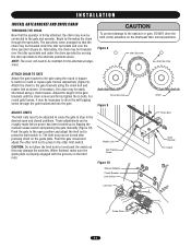
...brackets until the chain is firmly attached, the chain may be roughly made before power has been hooked up by flipping the manual release switch and pushing the gate manually (Figure 10). NOTE: The cover will need to be adjusted to cause the gate to stop in . Attach the chain...the chain bolt and master link as this may damage the switches. Chain Bolt Master Link Self Tapping Screw Figure 10 ADVERTENCIA PRECAUCIÓN Manual Release Circuit Breaker Limit Switch Gate Bracket U-Bolt Limit Nut Guide Plate 11 These adjustments can be necessary to drive the self tapping screw...
...brackets until the chain is firmly attached, the chain may be roughly made before power has been hooked up by flipping the manual release switch and pushing the gate manually (Figure 10). NOTE: The cover will need to be adjusted to cause the gate to stop in . Attach the chain...the chain bolt and master link as this may damage the switches. Chain Bolt Master Link Self Tapping Screw Figure 10 ADVERTENCIA PRECAUCIÓN Manual Release Circuit Breaker Limit Switch Gate Bracket U-Bolt Limit Nut Guide Plate 11 These adjustments can be necessary to drive the self tapping screw...
SL930 Manual
Page 23
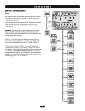
... that particular device. • See wiring diagrams shipped with kit for additional information. • See owner's manual for mounting, wiring, programming and adjustment. Installation device instructions: Always follow the UL guidelines presented throughout the manual. If these instructions are based upon UL325, and include recommendations for assistance. 23 All inputs are to...
... that particular device. • See wiring diagrams shipped with kit for additional information. • See owner's manual for mounting, wiring, programming and adjustment. Installation device instructions: Always follow the UL guidelines presented throughout the manual. If these instructions are based upon UL325, and include recommendations for assistance. 23 All inputs are to...
SL930 Manual
Page 25
...moving. ALWAYS keep people and objects away from children. 6. Failure to gate hardware. Inspection and service should always be performed by a LiftMaster operator. When servicing, please do some "house cleaning" of INJURY or DEATH. 10. Keep the remote control away from the gate... switches may have to the operator it is observed or suspected. 3. Never use separate entrance. owner's manual. GATE. 7. Pedestrians MUST 4. The gate MUST use grease or silicone spray. 5. AVERTISSEMENT DESCRIPTION External Entrapment Protection Systems Gate Caution Signs...
...moving. ALWAYS keep people and objects away from children. 6. Failure to gate hardware. Inspection and service should always be performed by a LiftMaster operator. When servicing, please do some "house cleaning" of INJURY or DEATH. 10. Keep the remote control away from the gate... switches may have to the operator it is observed or suspected. 3. Never use separate entrance. owner's manual. GATE. 7. Pedestrians MUST 4. The gate MUST use grease or silicone spray. 5. AVERTISSEMENT DESCRIPTION External Entrapment Protection Systems Gate Caution Signs...
SL930 Manual
Page 27
... 4, 5, 7 and 10 while the gate operator is in mid-travel may be necessary to determine which input device may be stuck. 8. Check the manual release switch to make sure that appears to the device. If it is the radio receiver that the circuit breaker button is tripped, press it... may stop input device and/or replace faulty device. Check to see REMOTE CONTROL DOES NOT WORK. 5. It may be stuck in . 10. TROUBLESHOOTING SL930 TROUBLESHOOTING REMOTE CONTROL DOES NOT WORK 1. If any of any of the LEDs flicker or illuminate. 4. Watch the stop input LED on the circuit board...
... 4, 5, 7 and 10 while the gate operator is in mid-travel may be necessary to determine which input device may be stuck. 8. Check the manual release switch to make sure that appears to the device. If it is the radio receiver that the circuit breaker button is tripped, press it... may stop input device and/or replace faulty device. Check to see REMOTE CONTROL DOES NOT WORK. 5. It may be stuck in . 10. TROUBLESHOOTING SL930 TROUBLESHOOTING REMOTE CONTROL DOES NOT WORK 1. If any of any of the LEDs flicker or illuminate. 4. Watch the stop input LED on the circuit board...
SL930 Manual
Page 30
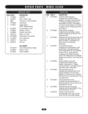
...Set Screws, Woodruff Key 1/4"x7/8", Shim Washer 1"x1.5"x.01", Shim Washer 1"x1.5"x.031", Hex Bolts 3/8-16x1, Flange Nuts 3/8-16 and E-Ring 1". Manual Release Circuit Breaker, 5 Amp Resistor, 10 Ohm Sonalert Piezo Alarm Battery, 12V 7AH Control Board, Full System 12V Transformer Relay 12Vdc Gear Box K79...Complete with: Sprocket 41B14-3/16" Keyway Includes 2 1/4" Set Screws, Bearing 1/2" IDx3/4" ODx1/2", Hex Bolt 5/8-11x2-3/4", Jam Hex Nuts 5/8-11 and Lockwasher 5/8. MODEL SL930 INDIVIDUAL PARTS ITEM PART # 1 13-40362 2 20-40351 3 9596 4 23-40050 5 23-40357 6 25-40356 7 29-40355 8 29-40089 9 29...
...Set Screws, Woodruff Key 1/4"x7/8", Shim Washer 1"x1.5"x.01", Shim Washer 1"x1.5"x.031", Hex Bolts 3/8-16x1, Flange Nuts 3/8-16 and E-Ring 1". Manual Release Circuit Breaker, 5 Amp Resistor, 10 Ohm Sonalert Piezo Alarm Battery, 12V 7AH Control Board, Full System 12V Transformer Relay 12Vdc Gear Box K79...Complete with: Sprocket 41B14-3/16" Keyway Includes 2 1/4" Set Screws, Bearing 1/2" IDx3/4" ODx1/2", Hex Bolt 5/8-11x2-3/4", Jam Hex Nuts 5/8-11 and Lockwasher 5/8. MODEL SL930 INDIVIDUAL PARTS ITEM PART # 1 13-40362 2 20-40351 3 9596 4 23-40050 5 23-40357 6 25-40356 7 29-40355 8 29-40089 9 29...


