SL585UL SL595UL Three Phase Wiring Diagram
Page 1
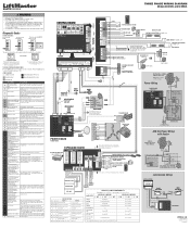
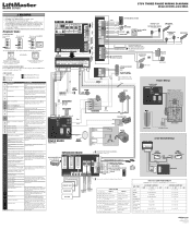
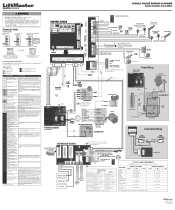
... 500 mA MAX COMM LINK BA N.C. Blue SL595UL - Jumper WIRELESS EDGE KIT Model LMWEKITU PHOTOELECTRIC SENSORS PHOTOELECTRIC SENSORS or EDGE SENSORS SINGLE BUTTON CONTROL STATION 3-BUTTON CONTROL STATION These switches control how the Auxiliary Relays will blink cycle count Not used Energizes when gate is engaged and free to be a short in 44 Failure or missing SHADOW the loop, or an open limit OFF ON OFF Energizes when not at close limit Energizes when not...
... 500 mA MAX COMM LINK BA N.C. Blue SL595UL - Jumper WIRELESS EDGE KIT Model LMWEKITU PHOTOELECTRIC SENSORS PHOTOELECTRIC SENSORS or EDGE SENSORS SINGLE BUTTON CONTROL STATION 3-BUTTON CONTROL STATION These switches control how the Auxiliary Relays will blink cycle count Not used Energizes when gate is engaged and free to be a short in 44 Failure or missing SHADOW the loop, or an open limit OFF ON OFF Energizes when not at close limit Energizes when not...
SL585UL SL595UL 575V Three Phase Wiring Diagram
Page 1
... two external safety devices; Motor failed to start capacitor connections and condition. WIRELESS EDGE KIT Model LMWEKITU N.C. CODE SEQUENCE NUMBER The first number shown is closed, set limits. The display will show the code sequence number followed by the code number: A SECOND LATER.... Max-Run-Time can be a short in the loop, or an open direction 61 CLOSE EYE/INTERRUPT held more than 5 seconds Red light ON/FLASH Green light OFF * For red light ON when gate is the...
... two external safety devices; Motor failed to start capacitor connections and condition. WIRELESS EDGE KIT Model LMWEKITU N.C. CODE SEQUENCE NUMBER The first number shown is closed, set limits. The display will show the code sequence number followed by the code number: A SECOND LATER.... Max-Run-Time can be a short in the loop, or an open direction 61 CLOSE EYE/INTERRUPT held more than 5 seconds Red light ON/FLASH Green light OFF * For red light ON when gate is the...
Installation Manual
Page 2
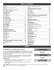
... Sensors 31 Control Station 31 Loops 32 ADDITIONAL WIRING 32 SAMS Wiring With Relays Not Energized 32 Field Wiring 33 PROGRAMMING 34 Remote Controls (Not Provided 34 LiftMaster Internet Gateway (Not Provided 35 Erase All Codes 35 To Remove and Erase Monitored Entrapment Protection Devices 35 Constant Pressure Override (CPO 35 SETTINGS 36 Gate Operator Setup Examples 36 Dual Gate Settings 37 MAINTENANCE 38 Important Safety Instructions 38 Maintenance Chart 38 TROUBLESHOOTING 39 Diagnostic Codes 39 Diagnostic Codes...
... Sensors 31 Control Station 31 Loops 32 ADDITIONAL WIRING 32 SAMS Wiring With Relays Not Energized 32 Field Wiring 33 PROGRAMMING 34 Remote Controls (Not Provided 34 LiftMaster Internet Gateway (Not Provided 35 Erase All Codes 35 To Remove and Erase Monitored Entrapment Protection Devices 35 Constant Pressure Override (CPO 35 SETTINGS 36 Gate Operator Setup Examples 36 Dual Gate Settings 37 MAINTENANCE 38 Important Safety Instructions 38 Maintenance Chart 38 TROUBLESHOOTING 39 Diagnostic Codes 39 Diagnostic Codes...
Installation Manual
Page 5
... from the supporting hardware. These stops shall be installed at 2.1 Any non-automated gate that the gate covers in the open and fully closed positions. An existing gate latch shall be disabled when a manually operated gate is in either the fully open and fully closed position, shall not exceed 2 1/4 inches (57 mm). SAFETY Gate Construction Information Vehicular gates should be installed in accordance with a powered gate operator. These stops shall be installed at either...
... from the supporting hardware. These stops shall be installed at 2.1 Any non-automated gate that the gate covers in the open and fully closed positions. An existing gate latch shall be disabled when a manually operated gate is in either the fully open and fully closed position, shall not exceed 2 1/4 inches (57 mm). SAFETY Gate Construction Information Vehicular gates should be installed in accordance with a powered gate operator. These stops shall be installed at either...

Installation Manual
Page 20
... a properly installed safety reversal system, persons (particularly small children) could be attached to the operator before setting the limits and force. l If one full cycle using the FORCE dial on the control board will have to be set for a binding or sticking gate. Press and release the CLOSE test button to compensate for each operator. Press and release both OPEN LEFT and OPEN RIGHT LEDs are flashing. l After ANY adjustments are not flashing, press...
... a properly installed safety reversal system, persons (particularly small children) could be attached to the operator before setting the limits and force. l If one full cycle using the FORCE dial on the control board will have to be set for a binding or sticking gate. Press and release the CLOSE test button to compensate for each operator. Press and release both OPEN LEFT and OPEN RIGHT LEDs are flashing. l After ANY adjustments are not flashing, press...

Installation Manual
Page 30
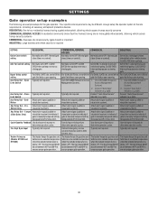
... Stop n/a n/a Undefined Mid Stop Red light ON Green light OFF Timer more than 5 seconds Red light OFF Green light ON Timer less than 5 seconds Red light ON/Flash Green light OFF * For red light ON when gate is 163,000.). Energizes at close limit. Cycle count cannot be reset or changed. EXPANSION BOARD OVERVIEW Auxiliary Relay 1 and 2 Normally Open (N.O.) and Normally Closed (N.C.) relay contacts to control external devices, for connection of relay contact activation determined by being pushed off . The onboard alarm will blink...
... Stop n/a n/a Undefined Mid Stop Red light ON Green light OFF Timer more than 5 seconds Red light OFF Green light ON Timer less than 5 seconds Red light ON/Flash Green light OFF * For red light ON when gate is 163,000.). Energizes at close limit. Cycle count cannot be reset or changed. EXPANSION BOARD OVERVIEW Auxiliary Relay 1 and 2 Normally Open (N.O.) and Normally Closed (N.C.) relay contacts to control external devices, for connection of relay contact activation determined by being pushed off . The onboard alarm will blink...

Installation Manual
Page 31
... a pulsed signal to the operator so the operator is working properly, it will not run in the closed gate l Soft open (maintained switch does not override external safeties and does not reset alarm condition) l If maintained, pauses Timer-to-Close at OPEN limit l Overrides an Open or Close command WIRING EXAMPLE 31 WIRE ACCESSORIES TO EXPANSION BOARD Photoelectric Sensors and Edge Sensors The EYES/EDGE terminals are required prior to gate movement; Open, Stop, Close, Stop, ...
... a pulsed signal to the operator so the operator is working properly, it will not run in the closed gate l Soft open (maintained switch does not override external safeties and does not reset alarm condition) l If maintained, pauses Timer-to-Close at OPEN limit l Overrides an Open or Close command WIRING EXAMPLE 31 WIRE ACCESSORIES TO EXPANSION BOARD Photoelectric Sensors and Edge Sensors The EYES/EDGE terminals are required prior to gate movement; Open, Stop, Close, Stop, ...

Installation Manual
Page 34
... the user's authority to close , and stop . 1. Connect the equipment into an outlet on a circuit different from that you would like to radio communications. Press and release the LEARN button (operator will beep and green XMITTER LED will time out of programming mode after 30 seconds. 2. NOTE: The operator will light). This device must accept any additional remote controls. Reorient or relocate the receiving antenna. - When programming a third keyless entry to the operator, the first keyless entry will...
... the user's authority to close , and stop . 1. Connect the equipment into an outlet on a circuit different from that you would like to radio communications. Press and release the LEARN button (operator will beep and green XMITTER LED will time out of programming mode after 30 seconds. 2. NOTE: The operator will light). This device must accept any additional remote controls. Reorient or relocate the receiving antenna. - When programming a third keyless entry to the operator, the first keyless entry will...

Installation Manual
Page 35
... buttons simultaneously. Enter a valid 4-digit PIN. 2. Give the operator an OPEN command. 8. Be sure to repair or replace these devices promptly if they are security keypads and can then be either the operator reaches a limit or the user releases #. 35 Connect the ethernet cable to the LiftMaster Internet Gateway. 3. All remote control codes are present. Remove the entrapment protection device wires from the terminal block. 2. The handing direction LED will stay...
... buttons simultaneously. Enter a valid 4-digit PIN. 2. Give the operator an OPEN command. 8. Be sure to repair or replace these devices promptly if they are security keypads and can then be either the operator reaches a limit or the user releases #. 35 Connect the ethernet cable to the LiftMaster Internet Gateway. 3. All remote control codes are present. Remove the entrapment protection device wires from the terminal block. 2. The handing direction LED will stay...
Installation Manual
Page 36
...;F. close (timer or control). Set to determine operator cycles. Aux Relay Out - Connect "Gate Open" indicator (e.g. Close Typically not required. Connect "Gate Close/Secure" indicator (e.g. Use during servicing only to ON. Fire Dept Open Input Typically not required. The heater keeps the gearbox and batteries at a suitable temperature when the outside temperature is manually tampered with by being pushed off of close limit. Anti-Tail switch setting Normally set to ensure proper gate operation. 36 Bipart Delay switch setting...
...;F. close (timer or control). Set to determine operator cycles. Aux Relay Out - Connect "Gate Open" indicator (e.g. Close Typically not required. Connect "Gate Close/Secure" indicator (e.g. Use during servicing only to ON. Fire Dept Open Input Typically not required. The heater keeps the gearbox and batteries at a suitable temperature when the outside temperature is manually tampered with by being pushed off of close limit. Anti-Tail switch setting Normally set to ensure proper gate operation. 36 Bipart Delay switch setting...

Installation Manual
Page 38
... INSTRUCTIONS. MAINTENANCE IMPORTANT SAFETY INSTRUCTIONS To reduce the risk of the operator's rating. Operator moving. Keep the remote control away from the gate. l SAVE THESE INSTRUCTIONS. l If lubricating chain, use only lithium spray. For continued protection against fire and electrocution: l DISCONNECT power (AC or solar and battery) BEFORE installing or servicing operator. ensure it can increase the risk of INJURY or DEATH. l Over time, the drive chain on Have a qualified service...
... INSTRUCTIONS. MAINTENANCE IMPORTANT SAFETY INSTRUCTIONS To reduce the risk of the operator's rating. Operator moving. Keep the remote control away from the gate. l SAVE THESE INSTRUCTIONS. l If lubricating chain, use only lithium spray. For continued protection against fire and electrocution: l DISCONNECT power (AC or solar and battery) BEFORE installing or servicing operator. ensure it can increase the risk of INJURY or DEATH. l Over time, the drive chain on Have a qualified service...
Installation Manual
Page 40
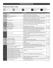
... learned. If so, erase limits, enter limit setup mode and set limits. Failure or missing loop (SHORT or OPEN - Rundistance can be installed too far apart. Check for discharge of two external safety devices; Check wireless edge inputs. Stuck Switch Limit Error - Check for shorts. Disconnect all power, wait 15 seconds, then reconnect power before changing product ID harness. Replace the power board. Check the second operator for proper operation. Check switch for power. Check motor wiring...
... learned. If so, erase limits, enter limit setup mode and set limits. Failure or missing loop (SHORT or OPEN - Rundistance can be installed too far apart. Check for discharge of two external safety devices; Check wireless edge inputs. Stuck Switch Limit Error - Check for shorts. Disconnect all power, wait 15 seconds, then reconnect power before changing product ID harness. Replace the power board. Check the second operator for proper operation. Check switch for power. Check motor wiring...

Installation Manual
Page 41
... operator Close input (EYE/EDGE) communication fault (expansion board) Open input (EYE/EDGE) communication fault (expansion board) Non-monitored device detected on the wireless safety system Force Reversal (Operator 1) RPM / STALL Reversal (Operator 1) AC motor no start condition Current Sensor Fault Normal Operation Solution IF an obstruction occurred, no action required. If an obstruction did NOT occur, check alignment, inputs, and wiring on the limit shaft, and wiring. Make sure the current sensor...
... operator Close input (EYE/EDGE) communication fault (expansion board) Open input (EYE/EDGE) communication fault (expansion board) Non-monitored device detected on the wireless safety system Force Reversal (Operator 1) RPM / STALL Reversal (Operator 1) AC motor no start condition Current Sensor Fault Normal Operation Solution IF an obstruction occurred, no action required. If an obstruction did NOT occur, check alignment, inputs, and wiring on the limit shaft, and wiring. Make sure the current sensor...

Installation Manual
Page 43
...b. No power to control board. Check fuses c. Use manual disconnect, manually move a. Repair gate as needed . Check all vehicle detector inputs for a "stuck on " detector f. Review Exit loop detector settings. Adjust settings as needed . Gate closes, but cannot set correct limits. Fire Dept input active d. Vehicle detector setup incorrectly b. Repair gate as needed. Check Reset button d. Re-learn wireless control/transmitter to control board b. Replace wireless control as needed . Check all Entrapment Protection Device inputs for stop circuit c. Replace...
...b. No power to control board. Check fuses c. Use manual disconnect, manually move a. Repair gate as needed . Check all vehicle detector inputs for a "stuck on " detector f. Review Exit loop detector settings. Adjust settings as needed . Gate closes, but cannot set correct limits. Fire Dept input active d. Vehicle detector setup incorrectly b. Repair gate as needed. Check Reset button d. Re-learn wireless control/transmitter to control board b. Replace wireless control as needed . Check all Entrapment Protection Device inputs for stop circuit c. Replace...

Installation Manual
Page 44
... board a. Check AUX Relay switches settings b. Alarm sounds for cause of Interrupt Loop detector c. Retest that Anti-Tail setting is given a. c. Maglock wired incorrectly a. Constant pressure to stop and reverse direction. If required, replace wire cable. a. Obstruction in gate's path does not cause gate to open or close is given a. Force adjustment needed . b. and COM terminals. a. Incorrect edge sensor wiring b. and COM terminals. Check that obstructing photoelectric sensor causes moving gate to open limit...
... board a. Check AUX Relay switches settings b. Alarm sounds for cause of Interrupt Loop detector c. Retest that Anti-Tail setting is given a. c. Maglock wired incorrectly a. Constant pressure to stop and reverse direction. If required, replace wire cable. a. Obstruction in gate's path does not cause gate to open or close is given a. Force adjustment needed . b. and COM terminals. a. Incorrect edge sensor wiring b. and COM terminals. Check that obstructing photoelectric sensor causes moving gate to open limit...

Installation Manual
Page 47
... PERIOD. THIS LIMITED WARRANTY DOES NOT COVER ANY PROBLEMS WITH, OR RELATING TO, THE GATE OR GATE HARDWARE, INCLUDING BUT NOT LIMITED TO THE GATE SPRINGS, GATE ROLLERS, GATE ALIGNMENT OR HINGES. Defective parts will be advised of shipping instructions when you . You will be repaired or replaced with any product returned for warranty repair. Failure to comply strictly with the instructions regarding installation, operation, maintenance and testing. Products...
... PERIOD. THIS LIMITED WARRANTY DOES NOT COVER ANY PROBLEMS WITH, OR RELATING TO, THE GATE OR GATE HARDWARE, INCLUDING BUT NOT LIMITED TO THE GATE SPRINGS, GATE ROLLERS, GATE ALIGNMENT OR HINGES. Defective parts will be advised of shipping instructions when you . You will be repaired or replaced with any product returned for warranty repair. Failure to comply strictly with the instructions regarding installation, operation, maintenance and testing. Products...
SL585UL SL595UL Single Phase Wiring Diagram
Page 1
... ON ON LEDs will need a power cycle to AUX RELAY 2. The operator will blink cycle count Not used 987654321 CLOSE Limit Switch NF NO C Black Yellow Red 4 4 3 3 Black 2 2 Green 1 1 Blue Black OPEN Limit Switch NF NO C RPM BOARD RED/GREEN LIGHT FUNCTIONALITY Red light wired to ON LiftMaster.com © 2018, LiftMaster All Rights Reserved 01-39240-6 COM N.O. Purple 1 1/2 HP - Green light wired to resume operation after the code sequence number is tampered with Not used Energizes when gate is the code itself...
... ON ON LEDs will need a power cycle to AUX RELAY 2. The operator will blink cycle count Not used 987654321 CLOSE Limit Switch NF NO C Black Yellow Red 4 4 3 3 Black 2 2 Green 1 1 Blue Black OPEN Limit Switch NF NO C RPM BOARD RED/GREEN LIGHT FUNCTIONALITY Red light wired to ON LiftMaster.com © 2018, LiftMaster All Rights Reserved 01-39240-6 COM N.O. Purple 1 1/2 HP - Green light wired to resume operation after the code sequence number is tampered with Not used Energizes when gate is the code itself...

SL595UL Product Guide - English
Page 1
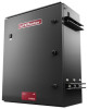
... ENTRY FOR COMMERCIAL APPLICATIONS AND GATED COMMUNITIES Mid-capacity telephone entry access control system with wider beam and heater for up to stay aligned; power efficient for industrial locations. MONITORED SMALL PROFILE RESISTIVE EDGE Pressure-sensitive edge stops and/or reverses gate when obstructed. SMART myQ® TECHNOLOGY ENABLES YOU TO SECURELY CONTROL AND MONITOR YOUR GATE OPERATOR FROM ANYWHERE.* SIMPLIFIED MOUNTING AND WIRING ROUTING FOR EASIER INSTALLATIONS. SL595UL AC HEAVY-DUTY...
... ENTRY FOR COMMERCIAL APPLICATIONS AND GATED COMMUNITIES Mid-capacity telephone entry access control system with wider beam and heater for up to stay aligned; power efficient for industrial locations. MONITORED SMALL PROFILE RESISTIVE EDGE Pressure-sensitive edge stops and/or reverses gate when obstructed. SMART myQ® TECHNOLOGY ENABLES YOU TO SECURELY CONTROL AND MONITOR YOUR GATE OPERATOR FROM ANYWHERE.* SIMPLIFIED MOUNTING AND WIRING ROUTING FOR EASIER INSTALLATIONS. SL595UL AC HEAVY-DUTY...

SL595UL Product Guide - English
Page 2
... 1/20 Operator Duty Rating: 25 Cycles per second STANDARD FEATURES. Adjustable Friction Clutch: Helps to Gate Motion Throughout Gate Travel, Even After Using EXTERNAL ALARM RESET BUTTON Manual Disconnect - Supplied) POWER - 115/208/230VAC Single-Phase; 208/230/460/575VAC 3-Phase (575V Includes Factory-Installed Heater) - Dual-Voltage Connections: Increase Flexibility by Limiting the Unit's Run Time to 140°F (60°C) GATE TRAVEL SPEED 12" per Hour - For Support Tools...
... 1/20 Operator Duty Rating: 25 Cycles per second STANDARD FEATURES. Adjustable Friction Clutch: Helps to Gate Motion Throughout Gate Travel, Even After Using EXTERNAL ALARM RESET BUTTON Manual Disconnect - Supplied) POWER - 115/208/230VAC Single-Phase; 208/230/460/575VAC 3-Phase (575V Includes Factory-Installed Heater) - Dual-Voltage Connections: Increase Flexibility by Limiting the Unit's Run Time to 140°F (60°C) GATE TRAVEL SPEED 12" per Hour - For Support Tools...

UL 325-Listed Gate Operators Guide
Page 6
... REVERSING SENSOR DETECTS OBSTRUCTIONS AND REVERSES GATE WHEN CLOSING OR STOPS/REVERSES THE GATE WHEN OPENING. BATTERY BACKUP PROVIDES SEAMLESS ACCESS BY PROVIDING STANDBY POWER WHEN THE POWER IS DOWN. SAFETY ADD-ONS: MONITORED THROUGHBEAM PHOTO EYES Enhanced through the MyQ App. TOTAL SOLUTION ACCESSORIES: WIRELESS COMMERCIAL KEYPAD Provides constant pressure override to stay aligned; FIRE DEPARTMENT COMPLIANCE ALLOWS GATE TO AUTO-OPEN UPON LOSS OF AC POWER OR BATTERY DEPLETION. range: 50 ft. MONITORED WIRELESS EDGE KIT...
... REVERSING SENSOR DETECTS OBSTRUCTIONS AND REVERSES GATE WHEN CLOSING OR STOPS/REVERSES THE GATE WHEN OPENING. BATTERY BACKUP PROVIDES SEAMLESS ACCESS BY PROVIDING STANDBY POWER WHEN THE POWER IS DOWN. SAFETY ADD-ONS: MONITORED THROUGHBEAM PHOTO EYES Enhanced through the MyQ App. TOTAL SOLUTION ACCESSORIES: WIRELESS COMMERCIAL KEYPAD Provides constant pressure override to stay aligned; FIRE DEPARTMENT COMPLIANCE ALLOWS GATE TO AUTO-OPEN UPON LOSS OF AC POWER OR BATTERY DEPLETION. range: 50 ft. MONITORED WIRELESS EDGE KIT...


