
LiftMaster SL585 Sell Sheet Manual
Page 4
... interrupt loop. per hour. OPERATOR WEIGHT 240 lbs. CONSTRUCTION P3 MOTOR® High starting torque continuous-duty motor. SPECIFICATIONS POWER 115/208/230 VAC. Voltage is a discrete model without field-selectable voltage. GATE TRAVEL SPEED 11 in synthetic oil bath. DUAL VOLTAGE CONNECTIONS Increase flexibility by limiting the unit's runtime to gate motion. ADJUSTABLE FRICTION CLUTCH Helps to protect gate and operator from being back-driven. Universal Single and 3-Button Remote Controls...
... interrupt loop. per hour. OPERATOR WEIGHT 240 lbs. CONSTRUCTION P3 MOTOR® High starting torque continuous-duty motor. SPECIFICATIONS POWER 115/208/230 VAC. Voltage is a discrete model without field-selectable voltage. GATE TRAVEL SPEED 11 in synthetic oil bath. DUAL VOLTAGE CONNECTIONS Increase flexibility by limiting the unit's runtime to gate motion. ADJUSTABLE FRICTION CLUTCH Helps to protect gate and operator from being back-driven. Universal Single and 3-Button Remote Controls...

LiftMaster Gate Operator Feature Chart Manual
Page 2
... Mechanical Mechanical Expansion Board Included (2) Aux Relays, Quick Close/ Yes Anti-Tailgate Yes Yes Yes Yes Yes Yes Plug-in -class features, see specific product sell sheets at LiftMaster.com power's down Security+ 2.0® 3 Channel Receiver Virtually eliminates interference and extends range Yes Yes Yes Yes Yes Yes Yes UP TO 50 REMOTE CONTROL CAPACITY FOR ALL GATE OPERATORS MyQ® Controls your gate from Yes...
... Mechanical Mechanical Expansion Board Included (2) Aux Relays, Quick Close/ Yes Anti-Tailgate Yes Yes Yes Yes Yes Yes Plug-in -class features, see specific product sell sheets at LiftMaster.com power's down Security+ 2.0® 3 Channel Receiver Virtually eliminates interference and extends range Yes Yes Yes Yes Yes Yes Yes UP TO 50 REMOTE CONTROL CAPACITY FOR ALL GATE OPERATORS MyQ® Controls your gate from Yes...

SL585151U Installation Manual
Page 3
... POWER WIRING 17 DUAL GATES ONLY 20 ADJUST THE HANDING AND LIMITS 22 ADJUST THE CLUTCH 23 OBSTRUCTION TEST 24 OPERATOR OVERVIEW 25 CONTROL BOARD OVERVIEW 26 CONTROL BOARD REFERENCE 26 LEARN BUTTON 27 DIAGNOSTIC DISPLAY 27 HANDING BUTTONS 27 BIPART DELAY 27 TIMER-TO-CLOSE (TTC 27 FORCE DIAL 28 TEST BUTTONS 28 STATUS LEDS 28 WIRE ACCESSORIES TO CONTROL BOARD 29 THREE BUTTON CONTROL STATION 29 FIRE DEPARTMENT 29 LOOPS 29 PHOTOELECTRIC SENSORS AND EDGE SENSORS...
... POWER WIRING 17 DUAL GATES ONLY 20 ADJUST THE HANDING AND LIMITS 22 ADJUST THE CLUTCH 23 OBSTRUCTION TEST 24 OPERATOR OVERVIEW 25 CONTROL BOARD OVERVIEW 26 CONTROL BOARD REFERENCE 26 LEARN BUTTON 27 DIAGNOSTIC DISPLAY 27 HANDING BUTTONS 27 BIPART DELAY 27 TIMER-TO-CLOSE (TTC 27 FORCE DIAL 28 TEST BUTTONS 28 STATUS LEDS 28 WIRE ACCESSORIES TO CONTROL BOARD 29 THREE BUTTON CONTROL STATION 29 FIRE DEPARTMENT 29 LOOPS 29 PHOTOELECTRIC SENSORS AND EDGE SENSORS...
SL585151U Installation Manual
Page 5
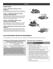
... gate controls. SAFETY USAGE CLASS CLASS I - CLASS III - INDUSTRIAL/LIMITED ACCESS VEHICULAR GATE OPERATOR A vehicular gate operator (or system) intended for use in garages or parking areas associated with the requirement; UL325 ENTRAPMENT PROTECTION REQUIREMENTS This vehicular gate operator must be used for use separate entrance. • SAVE THESE INSTRUCTIONS. 3 The gate MUST reverse on contact with Type A. After adjusting the force or the limit of INJURY or DEATH. • Use the emergency release...
... gate controls. SAFETY USAGE CLASS CLASS I - CLASS III - INDUSTRIAL/LIMITED ACCESS VEHICULAR GATE OPERATOR A vehicular gate operator (or system) intended for use in garages or parking areas associated with the requirement; UL325 ENTRAPMENT PROTECTION REQUIREMENTS This vehicular gate operator must be used for use separate entrance. • SAVE THESE INSTRUCTIONS. 3 The gate MUST reverse on contact with Type A. After adjusting the force or the limit of INJURY or DEATH. • Use the emergency release...

SL585151U Installation Manual
Page 6
... for the user as well as a component part of a swing gate. c. Locate the gate such that transmits radio frequency (RF) signals to reduce the risk of a swing gate is intended for exposed rollers. 5. b. One or more contact sensors shall be supplied with a separate access opening and closing to potential hazards. 3. The operator is supplied for installation only on each side of the reset control shall...
... for the user as well as a component part of a swing gate. c. Locate the gate such that transmits radio frequency (RF) signals to reduce the risk of a swing gate is intended for exposed rollers. 5. b. One or more contact sensors shall be supplied with a separate access opening and closing to potential hazards. 3. The operator is supplied for installation only on each side of the reset control shall...

SL585151U Installation Manual
Page 7
... be designed, constructed and installed such that portion of this specification. 2.2 This specification shall not apply to gates generally used for Exception. 3.1.4 Positive stops shall be required to limit travel . 1.8.2 Vehicular horizontal swing gate. These stops shall be installed at either the top of the gate, or at that time. 3. SAFETY GATE CONSTRUCTION INFORMATION Vehicular gates should be installed in contact with a moving gate,including any gate, refer to ASTM...
... be designed, constructed and installed such that portion of this specification. 2.2 This specification shall not apply to gates generally used for Exception. 3.1.4 Positive stops shall be required to limit travel . 1.8.2 Vehicular horizontal swing gate. These stops shall be installed at either the top of the gate, or at that time. 3. SAFETY GATE CONSTRUCTION INFORMATION Vehicular gates should be installed in contact with a moving gate,including any gate, refer to ASTM...

SL585151U Installation Manual
Page 14
... building codes before installation. PAD MOUNT INSTALLATION RETRO-FIT INSTALLATION The operator is recommended). 4. If you are replacing an SL580 and wish to angle in . NEW INSTALLATION 1. Secure operator to the concrete pad using four 1/2" concrete anchors (not provided). 4" (10.2 cm) (Gate) 1" (2.5 cm) (Conduit Location) 36" (91.4 cm) Drive and idler sprocket toward gate side 18" (45.7 cm) 1/2" Concrete Anchors (4 Required) 2" to 4" (5.1 to 10.2 cm) Above Grade Power and Control Wiring Must...
... building codes before installation. PAD MOUNT INSTALLATION RETRO-FIT INSTALLATION The operator is recommended). 4. If you are replacing an SL580 and wish to angle in . NEW INSTALLATION 1. Secure operator to the concrete pad using four 1/2" concrete anchors (not provided). 4" (10.2 cm) (Gate) 1" (2.5 cm) (Conduit Location) 36" (91.4 cm) Drive and idler sprocket toward gate side 18" (45.7 cm) 1/2" Concrete Anchors (4 Required) 2" to 4" (5.1 to 10.2 cm) Above Grade Power and Control Wiring Must...
SL585151U Installation Manual
Page 16
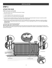
... aluminum. Vent Plug Pin Gate brackets must be used as a chain support. Remove the pin from bowing when chain is to add a brace along the length of idler sprocket. This may need to leave a maximum of 1" (2.5 cm) of chain slack for every 10' (3.1 m) of the gate. 2. Adjust nuts on the gear box. Do not overtighten chain. 7. Rear Gate Bracket Manual Release Handle 14 Front Gate Bracket Chain Guide Locate and engage the manual release handle and lock it in...
... aluminum. Vent Plug Pin Gate brackets must be used as a chain support. Remove the pin from bowing when chain is to add a brace along the length of idler sprocket. This may need to leave a maximum of 1" (2.5 cm) of chain slack for every 10' (3.1 m) of the gate. 2. Adjust nuts on the gear box. Do not overtighten chain. 7. Rear Gate Bracket Manual Release Handle 14 Front Gate Bracket Chain Guide Locate and engage the manual release handle and lock it in...
SL585151U Installation Manual
Page 18
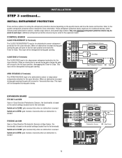
... ANTENNA CURRENT MOTOR DRIVE SENSOR ID RESET RPM & LIMITS ALARM EXP. This input will be wired to the expansion board. When an obstruction is sensed during gate opening. Refer to -Close. Additional entrapment protection devices may be disregarded during gate opening . CONTROL BOARD CLOSE EYES/INTERRUPT (2 Terminals) The CLOSE EYES/INTERRUPT input is for edge sensor entrapment protection for 4 seconds then stop. When an obstruction is sensed OPEN CLOSE TO MAIN BOARD Photoelectric Sensors 1 EYE ONLY 2 EYE/ EDGE 3 EYE...
... ANTENNA CURRENT MOTOR DRIVE SENSOR ID RESET RPM & LIMITS ALARM EXP. This input will be wired to the expansion board. When an obstruction is sensed during gate opening. Refer to -Close. Additional entrapment protection devices may be disregarded during gate opening . CONTROL BOARD CLOSE EYES/INTERRUPT (2 Terminals) The CLOSE EYES/INTERRUPT input is for edge sensor entrapment protection for 4 seconds then stop. When an obstruction is sensed OPEN CLOSE TO MAIN BOARD Photoelectric Sensors 1 EYE ONLY 2 EYE/ EDGE 3 EYE...

SL585151U Installation Manual
Page 22
... release the LEARN button again on the primary operator. The yellow NETWORK LED will time out of programming mode after 180 seconds. 3. Press and release the OPEN test button to be the network primary operator. The yellow NETWORK LED will beep) then turn off indicating successful deactivation. The yellow NETWORK LED will blink (operator will light. 3. Repeat the steps for 5 seconds. BIPART DELAY 4 2 6 OPEN LEFT OPEN 8 RIGHT HANDING OPEN GND ANTENNA CURRENT MOTOR DRIVE SENSOR ID RESET RPM & LIMITS...
... release the LEARN button again on the primary operator. The yellow NETWORK LED will time out of programming mode after 180 seconds. 3. Press and release the OPEN test button to be the network primary operator. The yellow NETWORK LED will beep) then turn off indicating successful deactivation. The yellow NETWORK LED will blink (operator will light. 3. Repeat the steps for 5 seconds. BIPART DELAY 4 2 6 OPEN LEFT OPEN 8 RIGHT HANDING OPEN GND ANTENNA CURRENT MOTOR DRIVE SENSOR ID RESET RPM & LIMITS...

SL585151U Installation Manual
Page 24
... fine tuned using the test buttons. Press and release either the OPEN RIGHT or OPEN LEFT button depending on contact with the OPEN limit switch at this cycle. SET THE HANDING 1. STEP 7 OPEN LEFT OPEN RIGHT ADJUST THE HANDING AND LIMITS HANDING The adjustments allow you set the limits but should be set to close position. For dual gate applications the limits will turn solid. Run the operator one control (force or travel . Gate MUST reverse on which...
... fine tuned using the test buttons. Press and release either the OPEN RIGHT or OPEN LEFT button depending on contact with the OPEN limit switch at this cycle. SET THE HANDING 1. STEP 7 OPEN LEFT OPEN RIGHT ADJUST THE HANDING AND LIMITS HANDING The adjustments allow you set the limits but should be set to close position. For dual gate applications the limits will turn solid. Run the operator one control (force or travel . Gate MUST reverse on which...

SL585151U Installation Manual
Page 26
... withstand the forces generated during motion, the operator will automatically reverse direction of the gate for the open gate and a rigid structure. If the gate does not reverse off the solid object, reduce the force setting by turning the force control slightly counter-clockwise. Place a solid object between the open direction. BIPART DELAY 4 2 6 OPEN LEFT OPEN 8 RIGHT HANDING GND ANTENNA CURRENT MOTOR DRIVE SENSOR ID RESET RPM & LIMITS ALARM EXP. Open and close the gate with an...
... withstand the forces generated during motion, the operator will automatically reverse direction of the gate for the open gate and a rigid structure. If the gate does not reverse off the solid object, reduce the force setting by turning the force control slightly counter-clockwise. Place a solid object between the open direction. BIPART DELAY 4 2 6 OPEN LEFT OPEN 8 RIGHT HANDING GND ANTENNA CURRENT MOTOR DRIVE SENSOR ID RESET RPM & LIMITS ALARM EXP. Open and close the gate with an...

SL585151U Installation Manual
Page 29
CONTROL BOARD OVERVIEW LEARN BUTTON The LEARN button is used to determine which indicates the operator type as "SL" followed by any signals from the open controls, loops, close edges, and close photoelectric sensors. 0 seconds (OFF) The gate will remain open limit. For more information about the codes refer to 180 seconds). NOTE: For gates installed on the control board prior to the TTC expiring will open and they are also used in dual gate applications where...
CONTROL BOARD OVERVIEW LEARN BUTTON The LEARN button is used to determine which indicates the operator type as "SL" followed by any signals from the open controls, loops, close edges, and close photoelectric sensors. 0 seconds (OFF) The gate will remain open limit. For more information about the codes refer to 180 seconds). NOTE: For gates installed on the control board prior to the TTC expiring will open and they are also used in dual gate applications where...

SL585151U Installation Manual
Page 38
...; remote controls and 2 keyless entries (1 PIN for open only. Press the OPEN, CLOSE, or STOP button, depending on the remote control for each remote control button 1. Operation is subject to program. However, there is full it will exit the programming mode and the remote control will time out of the FCC rules and Industry Canada (IC) licence-exempt RSS standard(s). NOTE: If installing an 86LM to close the gate. Press and release the LEARN button (operator will beep and green XMITTER LED...
...; remote controls and 2 keyless entries (1 PIN for open only. Press the OPEN, CLOSE, or STOP button, depending on the remote control for each remote control button 1. Operation is subject to program. However, there is full it will exit the programming mode and the remote control will time out of the FCC rules and Industry Canada (IC) licence-exempt RSS standard(s). NOTE: If installing an 86LM to close the gate. Press and release the LEARN button (operator will beep and green XMITTER LED...
SL585151U Installation Manual
Page 42
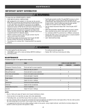
...; Over time, the drive chain on a separate fused line of adequate capacity. • NEVER let children operate or play with a rigid object or reverse when an object activates the noncontact sensors. To tighten the drive chain adjust either of travel . • SAVE THESE INSTRUCTIONS. To protect against fire: • Replace ONLY with national and local electrical codes. The gate MUST reverse on contact with gate controls. MAINTENANCE IMPORTANT SAFETY INFORMATION To reduce...
...; Over time, the drive chain on a separate fused line of adequate capacity. • NEVER let children operate or play with a rigid object or reverse when an object activates the noncontact sensors. To tighten the drive chain adjust either of travel . • SAVE THESE INSTRUCTIONS. To protect against fire: • Replace ONLY with national and local electrical codes. The gate MUST reverse on contact with gate controls. MAINTENANCE IMPORTANT SAFETY INFORMATION To reduce...
SL585151U Installation Manual
Page 44
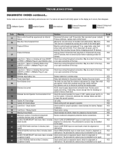
... board) Check wired input on expansion board; CLOSE EYE/EDGE held more than 3 minutes Check wired input on expansion board; check for power. If a code is not saved it occurs, then disappear. Max-Run-Time Exceeded Error Attempt to operator. Loop Error - LiftMaster Plug-in wireless edge. Wireless edge battery low Replace batteries in Loop Detector only) Check loop wiring throughout connection. Replace the power board. Run-distance can be re-learned by saving one ) not installed. Brownout occurred AC/DC board...
... board) Check wired input on expansion board; CLOSE EYE/EDGE held more than 3 minutes Check wired input on expansion board; check for power. If a code is not saved it occurs, then disappear. Max-Run-Time Exceeded Error Attempt to operator. Loop Error - LiftMaster Plug-in wireless edge. Wireless edge battery low Replace batteries in Loop Detector only) Check loop wiring throughout connection. Replace the power board. Run-distance can be re-learned by saving one ) not installed. Brownout occurred AC/DC board...

SL585151U Installation Manual
Page 45
... 43 TROUBLESHOOTING DIAGNOSTIC CODES continued... check for obstruction. Ensure operator is powered. See section on the current sensor. Replace RPM assembly. If the gate and motor ARE moving too slow, check for wiring issue or obstruction. Check the encoder cup and sensor on expansion board; If the fault continues, replace the power board. Some codes are saved in the mechanism, and relay board and start sequence failed. LiftMaster System Installed System Informational External...
... 43 TROUBLESHOOTING DIAGNOSTIC CODES continued... check for obstruction. Ensure operator is powered. See section on the current sensor. Replace RPM assembly. If the gate and motor ARE moving too slow, check for wiring issue or obstruction. Check the encoder cup and sensor on expansion board; If the fault continues, replace the power board. Some codes are saved in the mechanism, and relay board and start sequence failed. LiftMaster System Installed System Informational External...
SL585151U Installation Manual
Page 47
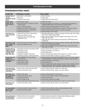
... AC power b) Check fuses c) Replace defective control board a) Check reset switch b) Check Stop button is stuck d) Poor radio reception Gate stops during a) Control (Open, Close) becoming active travel and reverses b) Vehicle loop detector active immediately. a) Check all Open and Close inputs for a "stuck on" input b) Check Stop button is too difficult to move Operator does not respond to a wired control/command (example: Open, Close, SBC, etc.) Operator does not respond to -Close. Check other wireless controls or devices. a) Review Interrupt loop detector settings. Adjust settings as...
... AC power b) Check fuses c) Replace defective control board a) Check reset switch b) Check Stop button is stuck d) Poor radio reception Gate stops during a) Control (Open, Close) becoming active travel and reverses b) Vehicle loop detector active immediately. a) Check all Open and Close inputs for a "stuck on" input b) Check Stop button is too difficult to move Operator does not respond to a wired control/command (example: Open, Close, SBC, etc.) Operator does not respond to -Close. Check other wireless controls or devices. a) Review Interrupt loop detector settings. Adjust settings as...
SL585151U Installation Manual
Page 48
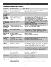
... Expansion board a) Check AUX Relay switches settings b) Check that Solenoid is connected to N.C. a) Check photoelectric sensor wiring. a) Check that wiring is wired to stop and reverse Photoelectric sensor does not stop and reverse direction. Alarm beeps when running. Retest that obstructing photoelectric sensor causes moving gate to stop or reverse b) Defective edge sensor gate. b) Replace defective edge sensor. TROUBLESHOOTING TROUBLESHOOTING CHART continued... SYMPTOM POSSIBLE CAUSES Shadow loop does not keep gate at open limit. a) Vehicle detector setup...
... Expansion board a) Check AUX Relay switches settings b) Check that Solenoid is connected to N.C. a) Check photoelectric sensor wiring. a) Check that wiring is wired to stop and reverse Photoelectric sensor does not stop and reverse direction. Alarm beeps when running. Retest that obstructing photoelectric sensor causes moving gate to stop or reverse b) Defective edge sensor gate. b) Replace defective edge sensor. TROUBLESHOOTING TROUBLESHOOTING CHART continued... SYMPTOM POSSIBLE CAUSES Shadow loop does not keep gate at open limit. a) Vehicle detector setup...
SL585151U Installation Manual
Page 51
... ASSUME FOR US ANY OTHER LIABILITY IN CONNECTION WITH THE SALE OF THIS PRODUCT. Some states do not allow limitations on your compliance with the instructions regarding installation, operation, maintenance and testing. THIS LIMITED WARRANTY DOES NOT COVER ANY PROBLEMS WITH, OR RELATING TO, THE GATE OR GATE HARDWARE, INCLUDING BUT NOT LIMITED TO THE GATE SPRINGS, GATE ROLLERS, GATE ALIGNMENT OR HINGES. Some states do...
... ASSUME FOR US ANY OTHER LIABILITY IN CONNECTION WITH THE SALE OF THIS PRODUCT. Some states do not allow limitations on your compliance with the instructions regarding installation, operation, maintenance and testing. THIS LIMITED WARRANTY DOES NOT COVER ANY PROBLEMS WITH, OR RELATING TO, THE GATE OR GATE HARDWARE, INCLUDING BUT NOT LIMITED TO THE GATE SPRINGS, GATE ROLLERS, GATE ALIGNMENT OR HINGES. Some states do...


