SL575 Manual
Page 2
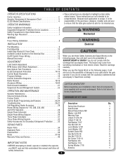
...Troubleshooting 26-27 Description Qty. Safety Installation Information 5 Suggested Entrapment Protection Device Locations 6 Safety Precautions for Open Roller Gates 7 Warning Sign Placement 7 WARNING Mechanical WIRING WARNING Power Wiring Installation 8 INSTALLATION CAUTION WARNING WEAlecRtriNcalING CAUTION Pad Mounting 9...or maintain the operator, Spring Washer 7/16 4 you MUST read and fully understand this Signal Word on the AVERT Manual Disconnect 12 ADJUSTMENT following pages, it will alert you to the possibility of damage to your installation check that all ...
...Troubleshooting 26-27 Description Qty. Safety Installation Information 5 Suggested Entrapment Protection Device Locations 6 Safety Precautions for Open Roller Gates 7 Warning Sign Placement 7 WARNING Mechanical WIRING WARNING Power Wiring Installation 8 INSTALLATION CAUTION WARNING WEAlecRtriNcalING CAUTION Pad Mounting 9...or maintain the operator, Spring Washer 7/16 4 you MUST read and fully understand this Signal Word on the AVERT Manual Disconnect 12 ADJUSTMENT following pages, it will alert you to the possibility of damage to your installation check that all ...
SL575 Manual
Page 5
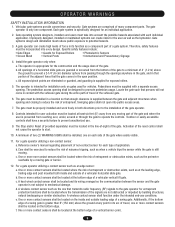
...as when a vehicle trips the sensor while the gate is still moving part of application. b. All openings of a gate system. The pedestrian access opening shall be located in contact with each individual application. Swinging gates shall not open position. The Stop and/or Reset (if ... safety features include: • Gate Edges • Screen Mesh • Guards for user activation must be located where the risk of many component parts. Reference owner's manual regarding placement of non-contact sensor for entrapment protection functions shall be located at the bottom ...
...as when a vehicle trips the sensor while the gate is still moving part of application. b. All openings of a gate system. The pedestrian access opening shall be located in contact with each individual application. Swinging gates shall not open position. The Stop and/or Reset (if ... safety features include: • Gate Edges • Screen Mesh • Guards for user activation must be located where the risk of many component parts. Reference owner's manual regarding placement of non-contact sensor for entrapment protection functions shall be located at the bottom ...
SL575 Manual
Page 13
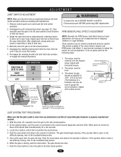
... and limit LEDs. Manually close the gate to its full open the gate to gauge the correct distance.) Adjust with horizontal screws. 2. When power is properly mounted and secured. 1. While the gate is built into both nuts. 4. The gate should begin opening , refer to spin freely. Adjust open limit switch. LIMIT DIRECTION DIRECTION OF GATE TO OPEN RIGHT (Factory Default...
... and limit LEDs. Manually close the gate to its full open the gate to gauge the correct distance.) Adjust with horizontal screws. 2. When power is properly mounted and secured. 1. While the gate is built into both nuts. 4. The gate should begin opening , refer to spin freely. Adjust open limit switch. LIMIT DIRECTION DIRECTION OF GATE TO OPEN RIGHT (Factory Default...
SL575 Manual
Page 17
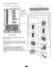
... Control Board SINGLE PHASE BOX NOTE: See wiring diagrams shipped with the gate while operating the controls where the user has full view of gate operation. *We strongly recommend that are contrary to operate the gate system, must be installed where the user cannot come into contact with ...Always follow the UL guidelines presented throughout the manual. Accessory Terminal Block 11 22 33 44 55 66 77 88 99 1100 1111 1122 1133 1144 1155 1166 1177 1188 1199 2200 Close Override Control Input (N.O.) OPEN CLOSE STOP Stop/Reset Control Input (N.O.) OPEN CLOSE STOP Shadow Loop Input (N.O.) Radio ...
... Control Board SINGLE PHASE BOX NOTE: See wiring diagrams shipped with the gate while operating the controls where the user has full view of gate operation. *We strongly recommend that are contrary to operate the gate system, must be installed where the user cannot come into contact with ...Always follow the UL guidelines presented throughout the manual. Accessory Terminal Block 11 22 33 44 55 66 77 88 99 1100 1111 1122 1133 1144 1155 1166 1177 1188 1199 2200 Close Override Control Input (N.O.) OPEN CLOSE STOP Stop/Reset Control Input (N.O.) OPEN CLOSE STOP Shadow Loop Input (N.O.) Radio ...
SL575 Manual
Page 18
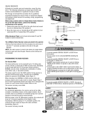
...recommend that you follow the UL guidelines presented throughout the manual. Refer to Terminal Block TB1 position 1. PROGRAMMING THE ...Terminals Jumper AVERT HIGH AVERT NORMAL ADVERTENCIA SECURITY MODE SECURITY MODE ATTEN WARNING The LiftMaster Radio Receiver comes pre-wired to operate at NORMAL position to the operator • Remove the... • Activate gate or door ONLY when it WARNING Connector Antenna onto the "F"-connector provided on residential openers is not connected BEFORE installing the receiver. ATTENTION When changing from a moving gate or door. CONSTANT...
...recommend that you follow the UL guidelines presented throughout the manual. Refer to Terminal Block TB1 position 1. PROGRAMMING THE ...Terminals Jumper AVERT HIGH AVERT NORMAL ADVERTENCIA SECURITY MODE SECURITY MODE ATTEN WARNING The LiftMaster Radio Receiver comes pre-wired to operate at NORMAL position to the operator • Remove the... • Activate gate or door ONLY when it WARNING Connector Antenna onto the "F"-connector provided on residential openers is not connected BEFORE installing the receiver. ATTENTION When changing from a moving gate or door. CONSTANT...
SL575 Manual
Page 26
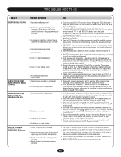
.... Failure to operator. Remove the accessory and test the operator. ➤ If the open or interrupt (safety) loop LED is good, check to operator. Replace the contactor. ... by consulting the wiring specifications section on page 8 of this manual. ➤ Perform a visual inspection of this manual. ➤ Verify power supply to make sure there is a... the corresponding input. If the contactor stops chattering, find an alternate power source for dual gate operation 3) Master or second unit is not programmed correctly 4) Master/second connection not properly grounded...
.... Failure to operator. Remove the accessory and test the operator. ➤ If the open or interrupt (safety) loop LED is good, check to operator. Replace the contactor. ... by consulting the wiring specifications section on page 8 of this manual. ➤ Perform a visual inspection of this manual. ➤ Verify power supply to make sure there is a... the corresponding input. If the contactor stops chattering, find an alternate power source for dual gate operation 3) Master or second unit is not programmed correctly 4) Master/second connection not properly grounded...
SL575 Manual
Page 27
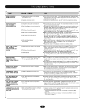
... the obstruction inputs to match the accessories that the unit's manual release is adjusted correctly but will run smoothly normally and reverse when encountering an obstruction. ➤ Disengage the manual release and roll gate open and close obstruction input has been programmed to move or binds..., repair the gate. ➤ Adjust the clutch so that it is not engaged. Locate and ...
... the obstruction inputs to match the accessories that the unit's manual release is adjusted correctly but will run smoothly normally and reverse when encountering an obstruction. ➤ Disengage the manual release and roll gate open and close obstruction input has been programmed to move or binds..., repair the gate. ➤ Adjust the clutch so that it is not engaged. Locate and ...


