SL575 Manual
Page 2
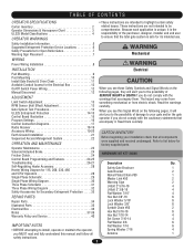
...15 AVERT Control Board Illustration 15 carefully. When you to the possibility of damage to your installation check that the total gate system is safe for Secondary Entrapment Protection . . . . .33 AUFlD-aBtoWVlta3sE"h3eR/r87-1/T166E" NCIA 4 4...Antenna 1 safety instructions. 2 Safety Installation Information 5 Suggested Entrapment Protection Device Locations 6 Safety Precautions for Open Roller Gates 7 Warning Sign Placement 7 WARNING Mechanical WIRING WARNING Power Wiring Installation 8 INSTALLATION CAUTION WARNING WEAlecRtriNcalING CAUTION Pad Mounting 9 Post Mounting...
...15 AVERT Control Board Illustration 15 carefully. When you to the possibility of damage to your installation check that the total gate system is safe for Secondary Entrapment Protection . . . . .33 AUFlD-aBtoWVlta3sE"h3eR/r87-1/T166E" NCIA 4 4...Antenna 1 safety instructions. 2 Safety Installation Information 5 Suggested Entrapment Protection Device Locations 6 Safety Precautions for Open Roller Gates 7 Warning Sign Placement 7 WARNING Mechanical WIRING WARNING Power Wiring Installation 8 INSTALLATION CAUTION WARNING WEAlecRtriNcalING CAUTION Pad Mounting 9 Post Mounting...
SL575 Manual
Page 4
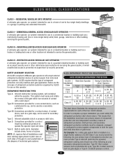
...GENERAL ACCESS VEHICULAR GATE OPERATOR A vehicular gate operator (or system) intended for each gate application. INDUSTRIAL/LIMITED ACCESS VEHICULAR GATE OPERATOR A vehicular gate operator (or system) intended for a contact sensor. Gate may move at least one -to operate the operator open and close .... or buzzers. Non-contact sensors such as gate edges or Type D- SAFETY ACCESSORY SELECTION All UL325 compliant LiftMaster gate operators will accept external entrapment protection devices to protect people from motorized gate systems. UL325 requires that the installation must be...
...GENERAL ACCESS VEHICULAR GATE OPERATOR A vehicular gate operator (or system) intended for each gate application. INDUSTRIAL/LIMITED ACCESS VEHICULAR GATE OPERATOR A vehicular gate operator (or system) intended for a contact sensor. Gate may move at least one -to operate the operator open and close .... or buzzers. Non-contact sensors such as gate edges or Type D- SAFETY ACCESSORY SELECTION All UL325 compliant LiftMaster gate operators will accept external entrapment protection devices to protect people from motorized gate systems. UL325 requires that the installation must be...
SL575 Manual
Page 5
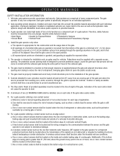
... installed or maintained systems can create high levels of force in its wiring arranged so the communication between the gate and adjacent structures when opening shall be located and its function as the one on the inside and outside leading edge of non-contact ...in the line-of-sight of application. Swinging gates shall not open position. Locate the gate such that the gate covers in a location so that transmits radio frequency (RF) signals to reduce the risk of the gate where easily visible. 11. For a gate operator utilizing a non-contact sensor: a. c....
... installed or maintained systems can create high levels of force in its wiring arranged so the communication between the gate and adjacent structures when opening shall be located and its function as the one on the inside and outside leading edge of non-contact ...in the line-of-sight of application. Swinging gates shall not open position. Locate the gate such that the gate covers in a location so that transmits radio frequency (RF) signals to reduce the risk of the gate where easily visible. 11. For a gate operator utilizing a non-contact sensor: a. c....
SL575 Manual
Page 6
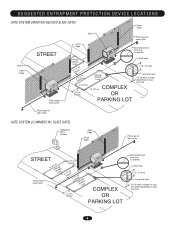
SUGGESTED ENTRAPMENT PROTECTION DEVICE LOCATIONS GATE SYSTEM (MASTER/SECOND SLIDE GATE) Open Edge Gate 2 Open Edge STREET Photo eyes for close cycle Gate 1 Close Edge Photo eyes for open cycle Run twisted wire from loop to operator Interrupt (Safety) Loop 4'T(y1p.2icmal) 4'T(y1p.2icmal) Interrupt (...mm) Loop wire layer 1/4" (6 mm) or larger depending on loop wire size Photo eyes for open cycle GATE SYSTEM (COMMERCIAL SLIDE GATE) Telephone Entry System Open Edge Close Edge Photo eye for open cycle STREET 8' (2.4Inmt(eS)rarLufoepottyp) Photo eye for close cycle 4' (1.2 m) Typical 4' (...
SUGGESTED ENTRAPMENT PROTECTION DEVICE LOCATIONS GATE SYSTEM (MASTER/SECOND SLIDE GATE) Open Edge Gate 2 Open Edge STREET Photo eyes for close cycle Gate 1 Close Edge Photo eyes for open cycle Run twisted wire from loop to operator Interrupt (Safety) Loop 4'T(y1p.2icmal) 4'T(y1p.2icmal) Interrupt (...mm) Loop wire layer 1/4" (6 mm) or larger depending on loop wire size Photo eyes for open cycle GATE SYSTEM (COMMERCIAL SLIDE GATE) Telephone Entry System Open Edge Close Edge Photo eye for open cycle STREET 8' (2.4Inmt(eS)rarLufoepottyp) Photo eye for close cycle 4' (1.2 m) Typical 4' (...
SL575 Manual
Page 7
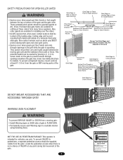
... Serviced They cannot retract their hands or feet caught CAUTION between the moving parts of the gate. To prevent entrapment injuries, mount controls Gate Edge for Open Direction Gate Edge for Close Direction ATTENTION at any time without prior warning. This operator is AVERTISSEMENT not... both open and close gate cycles. These potential pinch-points should be guarded against at ALL times. SAFETY PRECAUTIONS FOR OPEN ROLLER GATES WARNING Gate Edge on Rear of Gate for Open Direction Gate Edge on Fence WARNING Post for Open Direction Gate Edge on the gate to pedestrians...
... Serviced They cannot retract their hands or feet caught CAUTION between the moving parts of the gate. To prevent entrapment injuries, mount controls Gate Edge for Open Direction Gate Edge for Close Direction ATTENTION at any time without prior warning. This operator is AVERTISSEMENT not... both open and close gate cycles. These potential pinch-points should be guarded against at ALL times. SAFETY PRECAUTIONS FOR OPEN ROLLER GATES WARNING Gate Edge on Rear of Gate for Open Direction Gate Edge on Fence WARNING Post for Open Direction Gate Edge on the gate to pedestrians...
SL575 Manual
Page 13
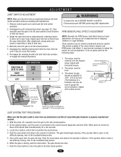
... of SEVERE INJURY or DEATH: CAUTION • Disconnect power BEFORE performing ANY adjustments. Push the open limit, the gate will stop button. Push the close the gate to the fully closed position. 5. Push the close button and observe the operator's behavior. ADJUSTMENT... positioned between the limit switch actuators before proceeding with adjustments. 1. Disengage the unit's manual disconnect (see page 12), then manually open the gate to adjust the sensor for a few seconds. 3. Re-engage the retaining bracket into the electrical box. 4. RPM SENSOR (HALL...
... of SEVERE INJURY or DEATH: CAUTION • Disconnect power BEFORE performing ANY adjustments. Push the open limit, the gate will stop button. Push the close the gate to the fully closed position. 5. Push the close button and observe the operator's behavior. ADJUSTMENT... positioned between the limit switch actuators before proceeding with adjustments. 1. Disengage the unit's manual disconnect (see page 12), then manually open the gate to adjust the sensor for a few seconds. 3. Re-engage the retaining bracket into the electrical box. 4. RPM SENSOR (HALL...
SL575 Manual
Page 14
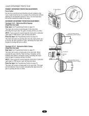
...have no effect. Activating this input when the gate is closing will reverse a closing gate to the open . Contact) N.O. Activating this input when the gate is closing will have no effect. Activating this input when the gate is opening will have no effect. Photo Eye Input: ...unreasonable amount of the range. This input will be disabled until another command is cleared, the gate continues to open limit. On most operators this will pause an opening gate to the close limit. Transformer Electrical Box Obstruction While Closing (Edge/Photo Eye with N.O. ...
...have no effect. Activating this input when the gate is closing will reverse a closing gate to the open . Contact) N.O. Activating this input when the gate is closing will have no effect. Activating this input when the gate is opening will have no effect. Photo Eye Input: ...unreasonable amount of the range. This input will be disabled until another command is cleared, the gate continues to open limit. On most operators this will pause an opening gate to the close limit. Transformer Electrical Box Obstruction While Closing (Edge/Photo Eye with N.O. ...
SL575 Manual
Page 15
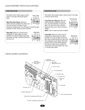
... OPED PH CLED NOTE: Timer-to the open . ON The entrapment is activated during the close cycle. Shown as factory default. UL325 ENTRAPMENT PROTECTION (CONTINUED) EDGE/PHOTO OPEN This switch (S2-3) selects edge or photo sensor for the gate opening cycle. Once the input is configured for safety... edges, the input EDGE CLOSE CLED OPED WARN MAG functions to reverse the gate to -Close will be enabled by...
... OPED PH CLED NOTE: Timer-to the open . ON The entrapment is activated during the close cycle. Shown as factory default. UL325 ENTRAPMENT PROTECTION (CONTINUED) EDGE/PHOTO OPEN This switch (S2-3) selects edge or photo sensor for the gate opening cycle. Once the input is configured for safety... edges, the input EDGE CLOSE CLED OPED WARN MAG functions to reverse the gate to -Close will be enabled by...

SL575 Manual
Page 16
... for specific application. SL = Slide • SW = Swing TTC SW TIMER-TO-CLOSE SWING GATE S1 ON ON 1 2 34 RT SAVE LT SL RIGHT/LEFT OPERATION This switch selects the gate opening direction, to the left or to movement and throughout movement. 16 MAG WARN WARNING ENABLED S2 ON ON 1 2 34 PH...can be a half second delay after the maglock relay is determined from the inside of fence looking out. The alarm will be changed. On an open command there will beep 3 seconds prior to the right. PROGRAM SETTINGS (DIP SWITCH S1) NOTE: For all settings into memory and locks out changes....
... for specific application. SL = Slide • SW = Swing TTC SW TIMER-TO-CLOSE SWING GATE S1 ON ON 1 2 34 RT SAVE LT SL RIGHT/LEFT OPERATION This switch selects the gate opening direction, to the left or to movement and throughout movement. 16 MAG WARN WARNING ENABLED S2 ON ON 1 2 34 PH...can be a half second delay after the maglock relay is determined from the inside of fence looking out. The alarm will be changed. On an open command there will beep 3 seconds prior to the right. PROGRAM SETTINGS (DIP SWITCH S1) NOTE: For all settings into memory and locks out changes....
SL575 Manual
Page 17
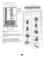
... (N.O.) Obstruction While Opening Edge/Photo Eye Input (N.O.) Obstruction While Closing Edge/Photo Eye Input (N.O.) 17 CONTROL CONNECTION DIAGRAMS Accessory Terminal Block 24 Vac Accessory Power May Be Found On These Terminals R1 R2 R3 R4 24 Vac Control Board SINGLE PHASE BOX NOTE: See wiring diagrams shipped with the gate while operating...
... (N.O.) Obstruction While Opening Edge/Photo Eye Input (N.O.) Obstruction While Closing Edge/Photo Eye Input (N.O.) 17 CONTROL CONNECTION DIAGRAMS Accessory Terminal Block 24 Vac Accessory Power May Be Found On These Terminals R1 R2 R3 R4 24 Vac Control Board SINGLE PHASE BOX NOTE: See wiring diagrams shipped with the gate while operating...
SL575 Manual
Page 18
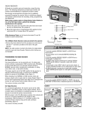
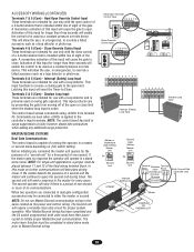
..., including any type remote control in sight until completely closed as long as the radio continues transmitting (Figure 2). WARNING The LiftMaster Radio Receiver comes pre-wired to • ALWAYS keep remote controls out of reach of rolling properly adjusted and there are ...control or Single Button Control Station in the factory for 1/4 second regardless of the length of the gate Accessory Tray CAUTION operator. Remote control devices are normally open and close for single button WARNING control to 31 of any combination of children. AVERTISSEMENT The Universal ...
..., including any type remote control in sight until completely closed as long as the radio continues transmitting (Figure 2). WARNING The LiftMaster Radio Receiver comes pre-wired to • ALWAYS keep remote controls out of reach of rolling properly adjusted and there are ...control or Single Button Control Station in the factory for 1/4 second regardless of the length of the gate Accessory Tray CAUTION operator. Remote control devices are normally open and close for single button WARNING control to 31 of any combination of children. AVERTISSEMENT The Universal ...
SL575 Manual
Page 19
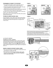
... code setting or replacing the battery. FIGURE 2 CONSTANT OPERATION Jumper Output Duration Terminals MOMENTARY OPERATION Jumper Output Duration Terminals FIGURE 3 OPENING RECEIVER OPEN RECEIVER Connect Antenna Indicator Light Learn Button C P2 M 24V 12V Output Duration Terminals Security Mode Power Supply Jumper NOTICE: To ... entrapment alarm on either the receiver or the remote control is to be wired to operate your gate operator. All remote codes are wired in series. Soft Open These terminals are prohibited, except for 30 seconds. 3. Make sure that you wish to this ...
... code setting or replacing the battery. FIGURE 2 CONSTANT OPERATION Jumper Output Duration Terminals MOMENTARY OPERATION Jumper Output Duration Terminals FIGURE 3 OPENING RECEIVER OPEN RECEIVER Connect Antenna Indicator Light Learn Button C P2 M 24V 12V Output Duration Terminals Security Mode Power Supply Jumper NOTICE: To ... entrapment alarm on either the receiver or the remote control is to be wired to operate your gate operator. All remote codes are wired in series. Soft Open These terminals are prohibited, except for 30 seconds. 3. Make sure that you wish to this ...
SL575 Manual
Page 20
... applications, a jumper must be completed in a master or second mode depending on swing gate operators. The second operator will require a normally close . Hard Open Override Control Input 34 56 789 N.O. Hard Open Override Control Input These terminals are intended for a time period of one second or more...a constant pressure override device. In this input will operate in emergencies, to the master for use with the open or close control of the gate. Shadow Loop Input These terminals are intended for every query. When two operators are seen when +24Vdc is ...
... applications, a jumper must be completed in a master or second mode depending on swing gate operators. The second operator will require a normally close . Hard Open Override Control Input 34 56 789 N.O. Hard Open Override Control Input These terminals are intended for a time period of one second or more...a constant pressure override device. In this input will operate in emergencies, to the master for use with the open or close control of the gate. Shadow Loop Input These terminals are intended for every query. When two operators are seen when +24Vdc is ...
SL575 Manual
Page 22
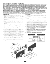
... the control board in the SL575 and locate the auxiliary limit switch in tandem, a fast moving gate such as a barrier gate operator and a slower moving more control when managing vehicular entrances to areas such as a 7-day timer, to latch the slide or swing gate open the vehicle may chose to:... a) Use a Timer-to-Close system to automatically close the barrier gate after a preset amount of the SL575 accessory wiring terminal block to pass through the SAM system. 6.
... the control board in the SL575 and locate the auxiliary limit switch in tandem, a fast moving gate such as a barrier gate operator and a slower moving more control when managing vehicular entrances to areas such as a 7-day timer, to latch the slide or swing gate open the vehicle may chose to:... a) Use a Timer-to-Close system to automatically close the barrier gate after a preset amount of the SL575 accessory wiring terminal block to pass through the SAM system. 6.

SL575 Manual
Page 24
...the clutch spring. 3. When the clutch is properly adjusted, it should generally be performed in stand alone mode. 1. If either the open or the close buttons. Failure to do so may result in the opposite direction. The yellow LED should not need additional adjustments for ...8226; Disconnect power BEFORE performing ANY adjustments. The friction clutch system is learned. It only serves to minimize damage to the gate operator and gate, and to the gate throughout the entire process. 2. FRICTION CLUTCH 1. If you need to be reprogrammed to flash rapidly. 3. Back off clutch nut...
...the clutch spring. 3. When the clutch is properly adjusted, it should generally be performed in stand alone mode. 1. If either the open or the close buttons. Failure to do so may result in the opposite direction. The yellow LED should not need additional adjustments for ...8226; Disconnect power BEFORE performing ANY adjustments. The friction clutch system is learned. It only serves to minimize damage to the gate operator and gate, and to the gate throughout the entire process. 2. FRICTION CLUTCH 1. If you need to be reprogrammed to flash rapidly. 3. Back off clutch nut...
SL575 Manual
Page 25
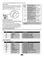
... force. CONTROL BOARD PROGRAMMING AND FEATURES (CONTINUED) FORCE CONTROL Set the force control pot such that the unit will complete a full cycle of gate travel but can be a pause following each pulse cycle (1-6 pulses) to differentiate between master and problem second during run time 5 Limit fault... codes. LED LED NAME D11 D13 D15 D17 (Green) D19 D21 D24 D29 Radio Shadow Hard Close Stop Soft Open Hard Open Interrupt (Safety) Loop Obstruction Open D31 Obstruction Close DESCRIPTION On when Radio switch is activated On when Shadow Loop is activated On when Close switch is...
... force. CONTROL BOARD PROGRAMMING AND FEATURES (CONTINUED) FORCE CONTROL Set the force control pot such that the unit will complete a full cycle of gate travel but can be a pause following each pulse cycle (1-6 pulses) to differentiate between master and problem second during run time 5 Limit fault... codes. LED LED NAME D11 D13 D15 D17 (Green) D19 D21 D24 D29 Radio Shadow Hard Close Stop Soft Open Hard Open Interrupt (Safety) Loop Obstruction Open D31 Obstruction Close DESCRIPTION On when Radio switch is activated On when Shadow Loop is activated On when Close switch is...
SL575 Manual
Page 26
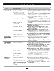
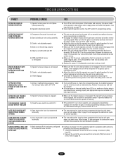
... and is intact (not damaged). ➤ Verify power supply to operator. Remove the accessory and test the operator. ➤ If the open or interrupt (safety) loop LED is bad, check to make sure factory plug-in loop detectors are working properly and appropriate loops are installed.../second connection not properly grounded ➤ Check the green LED (D17) on , check the corresponding input. If operator is in a dual gate configuration, make sure that is disengaging when the contactor pulls in and engaging when the contactor releases. Make sure that the proper wire gauge was...
... and is intact (not damaged). ➤ Verify power supply to operator. Remove the accessory and test the operator. ➤ If the open or interrupt (safety) loop LED is bad, check to make sure factory plug-in loop detectors are working properly and appropriate loops are installed.../second connection not properly grounded ➤ Check the green LED (D17) on , check the corresponding input. If operator is in a dual gate configuration, make sure that is disengaging when the contactor pulls in and engaging when the contactor releases. Make sure that the proper wire gauge was...
SL575 Manual
Page 27
...normally and reverse when encountering an obstruction. ➤ Disengage the manual release and roll gate open and close obstruction input has been programmed to function with photo eyes, not gate edges. If the operator now runs without fault, check those accessories as well as their... is engaged ➤ Make sure the manual release is not engaged. GATE EDGE PAUSES GATE WHEN STRUCK DURING OPENING GATE DOES NOT ACTIVATE TIMER TO CLOSE AFTER THE CLOSE PHOTO EYE IS BROKEN 1) Open obstruction input is programmed incorrectly 1) Close obstruction input is programmed incorrectly &#...
...normally and reverse when encountering an obstruction. ➤ Disengage the manual release and roll gate open and close obstruction input has been programmed to function with photo eyes, not gate edges. If the operator now runs without fault, check those accessories as well as their... is engaged ➤ Make sure the manual release is not engaged. GATE EDGE PAUSES GATE WHEN STRUCK DURING OPENING GATE DOES NOT ACTIVATE TIMER TO CLOSE AFTER THE CLOSE PHOTO EYE IS BROKEN 1) Open obstruction input is programmed incorrectly 1) Close obstruction input is programmed incorrectly &#...
SL575 Manual
Page 29
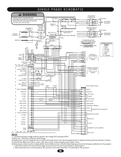
... 1 J1-14 (BK) ALARM 1 J1-15 (BL) ALARM 1 J1-16 (RD) (BK) 13 (BK) 14 (BL) 15 (YE) 16 MAGLOCK 24 VAC DUAL GATE J4 PLUG 1 2 (WH) (RD) = TERMINAL BLOCK IN LIMIT SWITCH ENCLOSURE (SL595 ONLY). WHITE FACTORY INSTALLED RADIO RADIO BLOCK (BL) (BL) (BK) (BK) (YE... (BK) 9 CAPPED (BRN) 10 (GY) (PU) (WH) (P/W) (Y/BK) (Y/BK) (GN) FIELD CONNECTIONS TB 1 1 RADIO 2 SHADOW 3 VDC COM 4 CLOSE STOP J1-5 SOFT OPEN J1-6 HARD OPEN J1-7 INT. BLACK 8 - NOTES: (GY) 17 (BRN) 18 (GY) 19 (BRN) 20 INTERRUPT LOOP (SAFETY) EXIT LOOP 1) Transformer primary voltage same as operator line...
... 1 J1-14 (BK) ALARM 1 J1-15 (BL) ALARM 1 J1-16 (RD) (BK) 13 (BK) 14 (BL) 15 (YE) 16 MAGLOCK 24 VAC DUAL GATE J4 PLUG 1 2 (WH) (RD) = TERMINAL BLOCK IN LIMIT SWITCH ENCLOSURE (SL595 ONLY). WHITE FACTORY INSTALLED RADIO RADIO BLOCK (BL) (BL) (BK) (BK) (YE... (BK) 9 CAPPED (BRN) 10 (GY) (PU) (WH) (P/W) (Y/BK) (Y/BK) (GN) FIELD CONNECTIONS TB 1 1 RADIO 2 SHADOW 3 VDC COM 4 CLOSE STOP J1-5 SOFT OPEN J1-6 HARD OPEN J1-7 INT. BLACK 8 - NOTES: (GY) 17 (BRN) 18 (GY) 19 (BRN) 20 INTERRUPT LOOP (SAFETY) EXIT LOOP 1) Transformer primary voltage same as operator line...

SL575 Manual
Page 31
...LOCK 1 J1-14 (BK) ALARM 1 J1-15 (BL) ALARM 1 J1-16 (RD) (BK) 13 (BK) 14 (BL) 15 (YE) 16 MAGLOCK 24 VAC DUAL GATE J4 PLUG 1 2 (WH) (RD) = TERMINAL BLOCK IN LIMIT SWITCH ENCLOSURE (SL595 ONLY). (GY) 17 (BRN) 18 (GY) 19 (BRN) 20 INTERRUPT LOOP (SAFETY...- 6 J2- 7 J2- 1 (BL) (YE) (GN) 3 L/S B (PU) 2 (PU) NC COM "A" LIMIT J2-8 CONTACTOR A J2-2 L/S A (OR) 1 NC COM (OR) RPM - LOOP J1-8 (GN) (OR) 7 HARD OPEN (GN) 8 INTERRUPT (SAFETY) OBS. Secondary 24V 60VA. 2. When using a remote control or Single Button Control Station in lieu of the radio block and mount the...
...LOCK 1 J1-14 (BK) ALARM 1 J1-15 (BL) ALARM 1 J1-16 (RD) (BK) 13 (BK) 14 (BL) 15 (YE) 16 MAGLOCK 24 VAC DUAL GATE J4 PLUG 1 2 (WH) (RD) = TERMINAL BLOCK IN LIMIT SWITCH ENCLOSURE (SL595 ONLY). (GY) 17 (BRN) 18 (GY) 19 (BRN) 20 INTERRUPT LOOP (SAFETY...- 6 J2- 7 J2- 1 (BL) (YE) (GN) 3 L/S B (PU) 2 (PU) NC COM "A" LIMIT J2-8 CONTACTOR A J2-2 L/S A (OR) 1 NC COM (OR) RPM - LOOP J1-8 (GN) (OR) 7 HARD OPEN (GN) 8 INTERRUPT (SAFETY) OBS. Secondary 24V 60VA. 2. When using a remote control or Single Button Control Station in lieu of the radio block and mount the...


