GSD Manual
Page 4
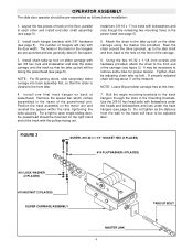
... the distance from the wall to the track will have to be adjusted later. Reel the chain around the drive sprocket, up bolt. Using the two 10-32 x 1-1/4 inch screws and hardware provided, attach the chain to the front end of track on the slider carriage using the master .... It may be mounted on the motor unit and reinstall the spacer within the rails, tightening the bolts securely. NOTE: Leave Bi-part slider carriage free at the midpoint. FIGURE 3 SCREW, #10-32 x 1-1/4" SOCKET HEX (2 PLACES) #10 FLATWASHER (4 PLACES) #10 LOCK WASHER (2 PLACES) #10 HEX NUT (2 PLACES) SLIDER CARRIAGE ...
... the distance from the wall to the track will have to be adjusted later. Reel the chain around the drive sprocket, up bolt. Using the two 10-32 x 1-1/4 inch screws and hardware provided, attach the chain to the front end of track on the slider carriage using the master .... It may be mounted on the motor unit and reinstall the spacer within the rails, tightening the bolts securely. NOTE: Leave Bi-part slider carriage free at the midpoint. FIGURE 3 SCREW, #10-32 x 1-1/4" SOCKET HEX (2 PLACES) #10 FLATWASHER (4 PLACES) #10 LOCK WASHER (2 PLACES) #10 HEX NUT (2 PLACES) SLIDER CARRIAGE ...

GSD Manual
Page 5
MOUNTING ASSEMBLY IDLER SHAFT ASSEMBLY ANGLE MOUNTING BRACKET FIGURE 4 HEX HEAD BOLT, 3/8-16 x 1" LONG (2 PER BRACKET) TRACK SPACER FLATWASHER, 1/8" (2 PER BRACKET) BI-PART SLIDER CARRIAGE (SEE FIGURE 2) SLIDER CARRIAGE (SEE FIGURE 1) POWERHEAD SERRATED FLANGE HEX NUT, #10 BI-PART SLIDER CARRIAGE HEX NUT, 3/8" (4 PER BRACKET) FLATWASHER, #10 (3 PER ASSEMBLY) FIGURE 5 SOCKET HEAD SCREW, 10-32 X 1-1/4" LONG (3PER ASSEMBLY) DRIVE CHAIN 5
MOUNTING ASSEMBLY IDLER SHAFT ASSEMBLY ANGLE MOUNTING BRACKET FIGURE 4 HEX HEAD BOLT, 3/8-16 x 1" LONG (2 PER BRACKET) TRACK SPACER FLATWASHER, 1/8" (2 PER BRACKET) BI-PART SLIDER CARRIAGE (SEE FIGURE 2) SLIDER CARRIAGE (SEE FIGURE 1) POWERHEAD SERRATED FLANGE HEX NUT, #10 BI-PART SLIDER CARRIAGE HEX NUT, 3/8" (4 PER BRACKET) FLATWASHER, #10 (3 PER ASSEMBLY) FIGURE 5 SOCKET HEAD SCREW, 10-32 X 1-1/4" LONG (3PER ASSEMBLY) DRIVE CHAIN 5

GSD Manual
Page 7
... door opening when door is provided to the slider with your operator for bipart door). NOTE: For bi-parting doors, it is necessary to bring the doors to itself around the weight so that the chain cannot move...the door as shown in the same manner. With both disconnect pins and engaged in their respective carriages, lift the drive chain over the three studs on each other door in figure 1. 2. However, a quick disconnect pin and chain mechanism... carriage. Cut off centerline of door (6 to 4 inches. 12. Adjust the screw collars on the other when the doors are fully closed. 13.
... door opening when door is provided to the slider with your operator for bipart door). NOTE: For bi-parting doors, it is necessary to bring the doors to itself around the weight so that the chain cannot move...the door as shown in the same manner. With both disconnect pins and engaged in their respective carriages, lift the drive chain over the three studs on each other door in figure 1. 2. However, a quick disconnect pin and chain mechanism... carriage. Cut off centerline of door (6 to 4 inches. 12. Adjust the screw collars on the other when the doors are fully closed. 13.


