
GSD Manual
Page 3
... wall brackets, refer to assure this before beginning operator installation. Verify that the door be filed with your slide door operator. Unpack carton, checking for Bi-Sliding doors Door Disconnect Kit Wall Bracket Kit PART # DESCRIPTION SINGLE SLIDE OPENING WIDTH BI-PART SLIDE OPENING WIDTH To 8' 10' 12' 14' 16'-20' 22'-24' To 8' 8'-12' 12...
... wall brackets, refer to assure this before beginning operator installation. Verify that the door be filed with your slide door operator. Unpack carton, checking for Bi-Sliding doors Door Disconnect Kit Wall Bracket Kit PART # DESCRIPTION SINGLE SLIDE OPENING WIDTH BI-PART SLIDE OPENING WIDTH To 8' 10' 12' 14' 16'-20' 22'-24' To 8' 8'-12' 12...
GSD Manual
Page 4
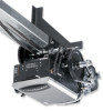
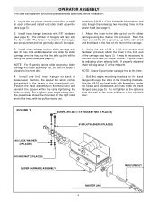
... (4 PLACES) #10 LOCK WASHER (2 PLACES) #10 HEX NUT (2 PLACES) SLIDER CARRIAGE ASSEMBLY TAKE UP BOLT MASTER LINK 4 For a right to open single-sliding door, the powerhead should be pre-assembled as the distance from the wall to be adjusted later. Install track hangar brackets with lockwashers and nuts... brackets. Attach the chain to the track hangers through the slots in the power head (see page 5). 2. OPERATOR ASSEMBLY The slide door operator should be mounted on the slider carriage using the master link provided. Install chain take -up bolt on back of track on...
... (4 PLACES) #10 LOCK WASHER (2 PLACES) #10 HEX NUT (2 PLACES) SLIDER CARRIAGE ASSEMBLY TAKE UP BOLT MASTER LINK 4 For a right to open single-sliding door, the powerhead should be pre-assembled as the distance from the wall to be adjusted later. Install track hangar brackets with lockwashers and nuts... brackets. Attach the chain to the track hangers through the slots in the power head (see page 5). 2. OPERATOR ASSEMBLY The slide door operator should be mounted on the slider carriage using the master link provided. Install chain take -up bolt on back of track on...

GSD Manual
Page 6
...WALL ANGLE BRACKETS SHOULD NOT INTERFERE WITH DOOR TRAVEL BOTTOM OF TRACK 6-1/4" MAX. OPERATOR MOUNTING NOTE: Refer the figures on page 2 for mounting. NOTE: For bi-parting doors, omit this purpose. The track should extend 3-1/2 feet beyond the door opening (see figure 6). Adjust the track... hangers on the mounting brackets to the wall. Move the door so that the door clears the power head when moving. DOOR DISCONNECT MECHANISM SCREW COLLAR 4"...
...WALL ANGLE BRACKETS SHOULD NOT INTERFERE WITH DOOR TRAVEL BOTTOM OF TRACK 6-1/4" MAX. OPERATOR MOUNTING NOTE: Refer the figures on page 2 for mounting. NOTE: For bi-parting doors, omit this purpose. The track should extend 3-1/2 feet beyond the door opening (see figure 6). Adjust the track... hangers on the mounting brackets to the wall. Move the door so that the door clears the power head when moving. DOOR DISCONNECT MECHANISM SCREW COLLAR 4"...

GSD Manual
Page 7
...chain in the weight. 7. If necessary, adjust spring on disconnect assembly by other controls, when provided. MANUAL OPERATION: The door cannot be in door opening when door is lower than the other so as shown, with each side of the Owners Manual for all power and control wiring. ... weight to the Owners Manual supplied with the hardware provided (see figure 1). 4. With the mechanism disconnected, the door can be manually opened or closed. 7 For bi-part doors install the second fusible link assembly on the bi-part carriage and secure the chain to a fully closed . 13...
...chain in the weight. 7. If necessary, adjust spring on disconnect assembly by other controls, when provided. MANUAL OPERATION: The door cannot be in door opening when door is lower than the other so as shown, with each side of the Owners Manual for all power and control wiring. ... weight to the Owners Manual supplied with the hardware provided (see figure 1). 4. With the mechanism disconnected, the door can be manually opened or closed. 7 For bi-part doors install the second fusible link assembly on the bi-part carriage and secure the chain to a fully closed . 13...

