MIRACLE ONE Manual
Page 2
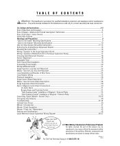
... permission of Maglock / Solenoid Relay Close Delay Option (Master / Second Only) Emergency Key Release Troubleshooting Optional Solar Power Miracle 1 Accessories Miracle 1 Parts Illustration Miracle 1 Parts List / Maintenance Features and Specifications Quick Reference Surge Suppressor Wiring Diagram 2-5 6 6 7 7 8 9...Board Description Alarm / Maglock Control Board Connections UL Audio Alarm Burglar Alarm and Proximity Switch "Gate Opening Inside" Installation of Maglock / Solenoid Relay "Gate Opening Outside" Installation of the publisher. Unless you are valid only if a correct assembly has...
... permission of Maglock / Solenoid Relay Close Delay Option (Master / Second Only) Emergency Key Release Troubleshooting Optional Solar Power Miracle 1 Accessories Miracle 1 Parts Illustration Miracle 1 Parts List / Maintenance Features and Specifications Quick Reference Surge Suppressor Wiring Diagram 2-5 6 6 7 7 8 9...Board Description Alarm / Maglock Control Board Connections UL Audio Alarm Burglar Alarm and Proximity Switch "Gate Opening Inside" Installation of Maglock / Solenoid Relay "Gate Opening Outside" Installation of the publisher. Unless you are valid only if a correct assembly has...
MIRACLE ONE Manual
Page 3
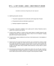
...device or devices must be located in the area of entrapment. Guarding is prevented from the gate so that the user is supplied for vehicles. Swinging gates shall not open into public access areas. E) Controls must be installed in a location so that enough clearance...use. A placard is supplied between the gate and adjacent structures when opening . ETL LISTINGS AND INSTRUCTIONS Installation Instructions Regarding the Gate Operator A) Install the gate operator only when: 1. C) The gate must be visible to the installation of the gate and be far enough from coming in ...
...device or devices must be located in the area of entrapment. Guarding is prevented from the gate so that the user is supplied for vehicles. Swinging gates shall not open into public access areas. E) Controls must be installed in a location so that enough clearance...use. A placard is supplied between the gate and adjacent structures when opening . ETL LISTINGS AND INSTRUCTIONS Installation Instructions Regarding the Gate Operator A) Install the gate operator only when: 1. C) The gate must be visible to the installation of the gate and be far enough from coming in ...
MIRACLE ONE Manual
Page 7
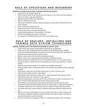
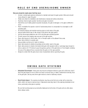
...8226; Be consistent with DASMA's Automatic Gate Opener System Safety Guide. ROLE OF SPECIFIERS AND DESIGNERS Specifiers and designers should : • Confirm that the gate operator being installed is appropriate for the application. • Confirm that the gate is designed and built according to current ...2 1/4 inch sphere to pass through any location, including the area of the adjacent fence covered when the gate is in the open position. • Install the gate operator according to the manufacturer's installation instructions. • Adjust the operator clutch or load-sensing device to the...
...8226; Be consistent with DASMA's Automatic Gate Opener System Safety Guide. ROLE OF SPECIFIERS AND DESIGNERS Specifiers and designers should : • Confirm that the gate operator being installed is appropriate for the application. • Confirm that the gate is designed and built according to current ...2 1/4 inch sphere to pass through any location, including the area of the adjacent fence covered when the gate is in the open position. • Install the gate operator according to the manufacturer's installation instructions. • Adjust the operator clutch or load-sensing device to the...
MIRACLE ONE Manual
Page 8
...anyone to climb under, over or through any portion of the gate below a 4 foot height, including the area of the adjacent fence covered when the gate is in the open position. • Always be certain that the gate area is opening. Be sure that warning signs are prominently displayed on both sides... of the gate and any area where gate motion is difficult to move , which can result in...
...anyone to climb under, over or through any portion of the gate below a 4 foot height, including the area of the adjacent fence covered when the gate is in the open position. • Always be certain that the gate area is opening. Be sure that warning signs are prominently displayed on both sides... of the gate and any area where gate motion is difficult to move , which can result in...
MIRACLE ONE Manual
Page 10
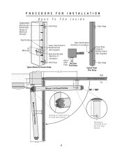
... Steel Bracket (Not Supplied) (Reinforce if necessary) Heavy Gate Hinge Typical Masonry Column Setup Steel Top View Plate Post Setup Gate Hinge Typical Steel 8.5" 25.75" Post Setup Out Gate in Closed Position 7.75" 6" In Miracle 1 in Closed Position 90° / 105° Gate in Open Position Miracle 1 in Open Position Indexing on central hole in the back...
... Steel Bracket (Not Supplied) (Reinforce if necessary) Heavy Gate Hinge Typical Masonry Column Setup Steel Top View Plate Post Setup Gate Hinge Typical Steel 8.5" 25.75" Post Setup Out Gate in Closed Position 7.75" 6" In Miracle 1 in Closed Position 90° / 105° Gate in Open Position Miracle 1 in Open Position Indexing on central hole in the back...
MIRACLE ONE Manual
Page 11
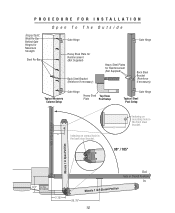
... necessary) Typical Masonry Column Setup Gate Hinge Heavy Steel Top View Plate Post Setup Gate Hinge Typical Steel Post Setup 6" Indexing on mounting hole in the front steel bracket. 6" 90° / 105° Gate in Open Position Miracle 1 in Open Position 8.5" This Plate Not Supplied 7.75" Out Gate in Closed Position In Miracle 1 in the back steel bracket...
... necessary) Typical Masonry Column Setup Gate Hinge Heavy Steel Top View Plate Post Setup Gate Hinge Typical Steel Post Setup 6" Indexing on mounting hole in the front steel bracket. 6" 90° / 105° Gate in Open Position Miracle 1 in Open Position 8.5" This Plate Not Supplied 7.75" Out Gate in Closed Position In Miracle 1 in the back steel bracket...
MIRACLE ONE Manual
Page 15
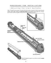
Slide to adjust. Re-tighten armature screws when gate positions are correct. Loosen the 2 screws of each armature to stop the gate in the "full open" and "full closed" positions. Position the outside limit switches of each limit switch armature. PROCEDURE FOR INSTALLATION Adjusting the ...Limit Switches Step 11: Adjust the travel distance of the gate with the 4 screws to complete the ...
Slide to adjust. Re-tighten armature screws when gate positions are correct. Loosen the 2 screws of each armature to stop the gate in the "full open" and "full closed" positions. Position the outside limit switches of each limit switch armature. PROCEDURE FOR INSTALLATION Adjusting the ...Limit Switches Step 11: Adjust the travel distance of the gate with the 4 screws to complete the ...
MIRACLE ONE Manual
Page 19
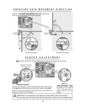
... The sensors must be adjusted while the gate is in the middle of the driveway, the sensor is to be turned to the corresponding position for the proper direction. 8 8 The gate opens inward. CHOOSING GATE MOVEMENT DIRECTION Switch the "Open Inside / Open Outside" switch on the control board to ..."yes" if the gate will look for the limit close first and then it will use positive stops...
... The sensors must be adjusted while the gate is in the middle of the driveway, the sensor is to be turned to the corresponding position for the proper direction. 8 8 The gate opens inward. CHOOSING GATE MOVEMENT DIRECTION Switch the "Open Inside / Open Outside" switch on the control board to ..."yes" if the gate will look for the limit close first and then it will use positive stops...
MIRACLE ONE Manual
Page 22
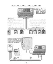
...the control board timer must be turned ON. 21 22 23 24 ® LAKE FOREST, CALIFORNIA www.eliteaccess.com Works as "Open Only" command To provide a close the gate. Works as "3 Push Button" control 123 456 789 HELP 0 REV A Elite Entry Phone Card Reader Digital Lock Push Button ...NOT let wire insulation interfere with connection. The First command will close command use #23 and #24. MIRACLE SURGE PROTECTION Important: Wiring at #21 and #22 will stop the gate. BLACK WHITE RED BROWN BLUE GREEN BLACK WHITE RED BROWN BLUE GREEN BURGLAR ALARM INPUT UL SENSOR CENTER ...
...the control board timer must be turned ON. 21 22 23 24 ® LAKE FOREST, CALIFORNIA www.eliteaccess.com Works as "Open Only" command To provide a close the gate. Works as "3 Push Button" control 123 456 789 HELP 0 REV A Elite Entry Phone Card Reader Digital Lock Push Button ...NOT let wire insulation interfere with connection. The First command will close command use #23 and #24. MIRACLE SURGE PROTECTION Important: Wiring at #21 and #22 will stop the gate. BLACK WHITE RED BROWN BLUE GREEN BLACK WHITE RED BROWN BLUE GREEN BURGLAR ALARM INPUT UL SENSOR CENTER ...

MIRACLE ONE Manual
Page 23
...Loop If there is no center loop, then F 4 ft If there is a center loop, then F = B or G which ever is for a typical single Miracle 1 loop installation. Individual circumstances may alter dimensions. If driveway is smaller than 18 ft, then D must be 4.5 ft If driveway is bigger than 18 ft..., then D must be a minimum of 4 feet away from open gate Center Loop B Outside D C Safety Loop A End of open gate! SINGLE OPERATOR LOOP SIZE AND PLACEMENT It is largest. Out In Drawing not to scale Exit Loop Inside H Safety Loop F I ...
...Loop If there is no center loop, then F 4 ft If there is a center loop, then F = B or G which ever is for a typical single Miracle 1 loop installation. Individual circumstances may alter dimensions. If driveway is smaller than 18 ft, then D must be 4.5 ft If driveway is bigger than 18 ft..., then D must be a minimum of 4 feet away from open gate Center Loop B Outside D C Safety Loop A End of open gate! SINGLE OPERATOR LOOP SIZE AND PLACEMENT It is largest. Out In Drawing not to scale Exit Loop Inside H Safety Loop F I ...

MIRACLE ONE Manual
Page 24
...18 ft, then D must be 4.5 ft If driveway is bigger than 18 ft, then D must have enough space between loops and gates to scale E Distance from open gate Out In Exit Loop Inside H Safety F Loop Center Loop Outside D C Safety A Loop I which ever is largest. This is for... a typical master/slave loop installation. Exit Loop H = G or I Outside Safety Loop: If A = Then C = 6 Feet 4 Feet G End of open gate B E Distance from open gate 9 Feet 4.5 Feet 12 Feet 5 Feet 15 Feet 5 Feet 18 Feet 5.5 Feet 21 Feet 6 Feet Center Loop: This loop must be a minimum of 4 feet ...
...18 ft, then D must be 4.5 ft If driveway is bigger than 18 ft, then D must have enough space between loops and gates to scale E Distance from open gate Out In Exit Loop Inside H Safety F Loop Center Loop Outside D C Safety A Loop I which ever is largest. This is for... a typical master/slave loop installation. Exit Loop H = G or I Outside Safety Loop: If A = Then C = 6 Feet 4 Feet G End of open gate B E Distance from open gate 9 Feet 4.5 Feet 12 Feet 5 Feet 15 Feet 5 Feet 18 Feet 5.5 Feet 21 Feet 6 Feet Center Loop: This loop must be a minimum of 4 feet ...

MIRACLE ONE Manual
Page 26
LOOP DETECTOR WIRING Safety Loop Allows gate to stay open for exiting vehicles. 25 OUT LSoaofepty L Coeonpter LSoaofepty LoEoxpit IN Exit Loop CENTER LOOP SAFETY LOOP STRIKE...23 24 25 26 27 Surge Suppressor Elite Part # A 24 Com N.O. Gnd +24V 21 22 23 25 Allows gate to stay open when vehicles are obstructing gate path. Gnd +24V 23 25 Elite Part # A 24 17 18 Com N.O. CENTER LOOP SAFETY LOOP STRIKE INPUT GROUND...20 Com N.O. Gnd +24V 23 25 For fail safe operation, connect safety loops in series. Center Loop Allows gate to automatically open when vehicles are obstructing...
LOOP DETECTOR WIRING Safety Loop Allows gate to stay open for exiting vehicles. 25 OUT LSoaofepty L Coeonpter LSoaofepty LoEoxpit IN Exit Loop CENTER LOOP SAFETY LOOP STRIKE...23 24 25 26 27 Surge Suppressor Elite Part # A 24 Com N.O. Gnd +24V 21 22 23 25 Allows gate to stay open when vehicles are obstructing gate path. Gnd +24V 23 25 Elite Part # A 24 17 18 Com N.O. CENTER LOOP SAFETY LOOP STRIKE INPUT GROUND...20 Com N.O. Gnd +24V 23 25 For fail safe operation, connect safety loops in series. Center Loop Allows gate to automatically open when vehicles are obstructing...
MIRACLE ONE Manual
Page 27
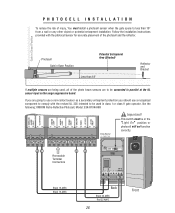
...C1) 2 (NC1) 4 5 6 240VDC 15 16 25 23 Black 16 AWG Black 16 AWG Back Black 22 AWG Red 22 AWG 26 Front Gate in Closed Position Photocell Gate in Open Position Potential Entrapment Area (Shaded) Less than 18" from a wall or any other object or potential entrapment installation. PHOTOCELL INSTALLATION To reduce the... sensors are being used in parallel at the UL sensor input on the surge suppression board. This switch must install a photocell sensor when the gate opens to comply with the photocell sensor for accurate placement of injury, You must be connected in class I or class II...
...C1) 2 (NC1) 4 5 6 240VDC 15 16 25 23 Black 16 AWG Black 16 AWG Back Black 22 AWG Red 22 AWG 26 Front Gate in Closed Position Photocell Gate in Open Position Potential Entrapment Area (Shaded) Less than 18" from a wall or any other object or potential entrapment installation. PHOTOCELL INSTALLATION To reduce the... sensors are being used in parallel at the UL sensor input on the surge suppression board. This switch must install a photocell sensor when the gate opens to comply with the photocell sensor for accurate placement of injury, You must be connected in class I or class II...
MIRACLE ONE Manual
Page 29
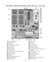
... 26 1 25 24 23 22 2 21 20 19 18 1 17 16 15 14 13 12 11 10 3 4 1 Open or Close Relay LED 2 Control Relay LED 3 Motor Fuse 4 J1-Batteries and Motor Connector 5 Strike Open LED 6 Safety Loop LED 7 Radio Receiver LED 8 Center Loop LED 9 J3 Transformer & Input Commands Connector 10 Central Control... 18 Timer Active LED 19 Timer Pot (3 to 60 sec.) 20 Switch-Timer, Off / On 21 Overlapping Gate, Off / On 22 Stop by Positive Stop Option Switch, No / Yes Close Delay 23 Switch-Open Inside / Outside 24 Alarm Sensor LED 25 Reverse Sensor Adjustment 26 Reverse Sensor LED 27 System On LED...
... 26 1 25 24 23 22 2 21 20 19 18 1 17 16 15 14 13 12 11 10 3 4 1 Open or Close Relay LED 2 Control Relay LED 3 Motor Fuse 4 J1-Batteries and Motor Connector 5 Strike Open LED 6 Safety Loop LED 7 Radio Receiver LED 8 Center Loop LED 9 J3 Transformer & Input Commands Connector 10 Central Control... 18 Timer Active LED 19 Timer Pot (3 to 60 sec.) 20 Switch-Timer, Off / On 21 Overlapping Gate, Off / On 22 Stop by Positive Stop Option Switch, No / Yes Close Delay 23 Switch-Open Inside / Outside 24 Alarm Sensor LED 25 Reverse Sensor Adjustment 26 Reverse Sensor LED 27 System On LED...
MIRACLE ONE Manual
Page 32
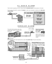
... Connector 1 2 3 4 COM N.O. Important: When interfacing with the unit to make your connections to these alarm outputs. Proximity Switch (Normally Open) If the gate is required per UL-325. WILL NOT reset alarm! SINGLE OR MASTER ONLY Second ONLY MOTOR BRAKE LIMITS MOTOR BRAKE LIMITS 12 3 456 7... #17 & #18 Safety Loop #19 & #20 UL Audio Alarm Radio Receiver #23 & #24 MIRACLE SURGE PROTECTION BURGLAR ALARM ® The control board provides a relay with a normally open without a valid command, the proximity switch will be activated, causing the house alarm to activate. 2" Max...
... Connector 1 2 3 4 COM N.O. Important: When interfacing with the unit to make your connections to these alarm outputs. Proximity Switch (Normally Open) If the gate is required per UL-325. WILL NOT reset alarm! SINGLE OR MASTER ONLY Second ONLY MOTOR BRAKE LIMITS MOTOR BRAKE LIMITS 12 3 456 7... #17 & #18 Safety Loop #19 & #20 UL Audio Alarm Radio Receiver #23 & #24 MIRACLE SURGE PROTECTION BURGLAR ALARM ® The control board provides a relay with a normally open without a valid command, the proximity switch will be activated, causing the house alarm to activate. 2" Max...
MIRACLE ONE Manual
Page 33
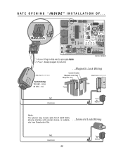
Always plugged in white wire to open gate Inside 2. Plug in (red wire) Control Board Elite Part # Q240 MAU Contact Rating 125 VAC - 0.5 A 30 VDC - 2 A ...Magnetic Lock Wiring Custom Bracket Magnetic Lock Plate Magnetic Lock Elite Part # A MG 1300 Gate Fence N.C. Common 32 Power for Maglock Note: The optional relay module (Elite Part # Q240...
Always plugged in white wire to open gate Inside 2. Plug in (red wire) Control Board Elite Part # Q240 MAU Contact Rating 125 VAC - 0.5 A 30 VDC - 2 A ...Magnetic Lock Wiring Custom Bracket Magnetic Lock Plate Magnetic Lock Elite Part # A MG 1300 Gate Fence N.C. Common 32 Power for Maglock Note: The optional relay module (Elite Part # Q240...

MIRACLE ONE Manual
Page 34
... module (Elite Part # Q240 MAU), allowing interface with external devices, is available, only from Chamberlain Elite. ...Solenoid Lock Wiring N.O. Always plugged in white wire to open gate Outside Control Board Elite Part # Q240 MAU Contact Rating 125 VAC - 0.5 A 30 VDC - 2 A ...Magnetic Lock Wiring Custom Bracket Magnetic Lock Plate Magnetic Lock Elite Part...
... module (Elite Part # Q240 MAU), allowing interface with external devices, is available, only from Chamberlain Elite. ...Solenoid Lock Wiring N.O. Always plugged in white wire to open gate Outside Control Board Elite Part # Q240 MAU Contact Rating 125 VAC - 0.5 A 30 VDC - 2 A ...Magnetic Lock Wiring Custom Bracket Magnetic Lock Plate Magnetic Lock Elite Part...
MIRACLE ONE Manual
Page 35
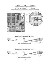
Second Master operator delays to close the gate. 34 Master Inside Property Master Inside Property Opening "Inside" and Overlap to the "Outside"... Second Master operator delays to be used when there is a Master/Second installation with overlapping gates. Opening "Inside" and Overlap to the "Inside"... CLOSE DELAY OPTION Master/Second Only This option is to close the gate.
Second Master operator delays to close the gate. 34 Master Inside Property Master Inside Property Opening "Inside" and Overlap to the "Outside"... Second Master operator delays to be used when there is a Master/Second installation with overlapping gates. Opening "Inside" and Overlap to the "Inside"... CLOSE DELAY OPTION Master/Second Only This option is to close the gate.
MIRACLE ONE Manual
Page 36
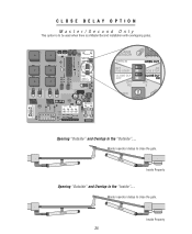
Master operator delays to close the gate. Second Master 35 Inside Property CLOSE DELAY OPTION Master/Second Only This option is to the "Outside"... Opening "Outside" and Overlap to be used when there is a Master/Second installation with overlapping gates. Second Master Inside Property Opening "Outside" and Overlap to close the gate. Master operator delays to the "Inside"...
Master operator delays to close the gate. Second Master 35 Inside Property CLOSE DELAY OPTION Master/Second Only This option is to the "Outside"... Opening "Outside" and Overlap to be used when there is a Master/Second installation with overlapping gates. Second Master Inside Property Opening "Outside" and Overlap to close the gate. Master operator delays to the "Inside"...
MIRACLE ONE Manual
Page 37
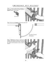
Full Open Position 90 Degrees Push or Pull Lock Click! 36 EMERGENCY KEY RELEASE Step 1: To move the gate during an emergency or power failure, insert key and turn counterclockwise to the full open position 90°. Step 3: Re-Lock the operator by turning the key clockwise while pushing or pulling on the gate until you hear the key release click into place. Unlock Key Provided Step 2: Move the gate manually to Unlock the Miracle 1 from the gate. The operator can resume normal operation as soon as power is restored.
Full Open Position 90 Degrees Push or Pull Lock Click! 36 EMERGENCY KEY RELEASE Step 1: To move the gate during an emergency or power failure, insert key and turn counterclockwise to the full open position 90°. Step 3: Re-Lock the operator by turning the key clockwise while pushing or pulling on the gate until you hear the key release click into place. Unlock Key Provided Step 2: Move the gate manually to Unlock the Miracle 1 from the gate. The operator can resume normal operation as soon as power is restored.


