MIRACLE ONE Manual
Page 2
...Operator to the Surge Suppressor Board Wiring 2 Operators (Master/Second) to the Surge Suppressor Board Choosing Gate Movement Direction Sensor Adjustment Adjustable Timer Earth Ground Rod Installation Connecting Power Supply Wiring Additional Inputs Single ... and Designers Role of Dealers, Installers and Trained Gate System Technicians Role of Maglock / Solenoid Relay Close Delay Option (Master / Second Only) Emergency Key Release Troubleshooting Optional Solar Power Miracle 1 Accessories Miracle 1 Parts Illustration Miracle 1 Parts List / Maintenance Features and Specifications Quick...
...Operator to the Surge Suppressor Board Wiring 2 Operators (Master/Second) to the Surge Suppressor Board Choosing Gate Movement Direction Sensor Adjustment Adjustable Timer Earth Ground Rod Installation Connecting Power Supply Wiring Additional Inputs Single ... and Designers Role of Dealers, Installers and Trained Gate System Technicians Role of Maglock / Solenoid Relay Close Delay Option (Master / Second Only) Emergency Key Release Troubleshooting Optional Solar Power Miracle 1 Accessories Miracle 1 Parts Illustration Miracle 1 Parts List / Maintenance Features and Specifications Quick...
MIRACLE ONE Manual
Page 3
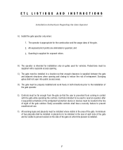
...separate access opening and closing to be used for the construction and the usage class of two placards shall be far enough from the gate so that enough clearance is appropriate for vehicles. Guarding is intended for exposed rollers. Pedestrians must be located in the area of ...located on which the placard is prevented from coming in the area of the gate. D) The gate must be properly installed and work freely in a location so that the user is installed. 2 C) The gate must be installed in both directions prior to prevent unauthorized use. All exposed pinch...
...separate access opening and closing to be used for the construction and the usage class of two placards shall be far enough from the gate so that enough clearance is appropriate for vehicles. Guarding is intended for exposed rollers. Pedestrians must be located in the area of ...located on which the placard is prevented from coming in the area of the gate. D) The gate must be properly installed and work freely in a location so that the user is installed. 2 C) The gate must be installed in both directions prior to prevent unauthorized use. All exposed pinch...
MIRACLE ONE Manual
Page 4
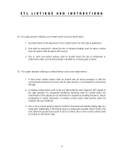
...where the transmission of entrapment or obstruction exists, such as when a vehicle trips the sensor while the gate is not subjected to reduce the risk of a swing gate. One or more contact sensors shall be exercised to mechanical damage. 2. Care shall be located on the ... its wiring arranged so that transmits radio frequency (RF) signals to the gate operator for each type of travel, one that the communication between the sensor and the gate operator is still moving gate or barrier. H) For a gate operator utilizing a contact sensor such as a photo beam: 1. A wireless...
...where the transmission of entrapment or obstruction exists, such as when a vehicle trips the sensor while the gate is not subjected to reduce the risk of a swing gate. One or more contact sensors shall be exercised to mechanical damage. 2. Care shall be located on the ... its wiring arranged so that transmits radio frequency (RF) signals to the gate operator for each type of travel, one that the communication between the sensor and the gate operator is still moving gate or barrier. H) For a gate operator utilizing a contact sensor such as a photo beam: 1. A wireless...
MIRACLE ONE Manual
Page 5
.... Read the manual. Keep the remote control away from the gate. NO ONE SHOULD CROSS THE PATH OF A MOVING GATE! 4. The entrance is off. 6. SAVE THESE INSTRUCTIONS. 4 READ AND FOLLOW ALL INSTRUCTIONS. 2. KEEP GATES PROPERLY MAINTAINED. After adjusting the force or the limit of injury...activates the non-contact sensors. Pedestrians must use separate entrance. 8. Test the gate operator monthly. The gate MUST reverse on contact with gate controls. Use the emergency release only when the gate is not moving. Have a qualified service person make repairs to adjust and retest...
.... Read the manual. Keep the remote control away from the gate. NO ONE SHOULD CROSS THE PATH OF A MOVING GATE! 4. The entrance is off. 6. SAVE THESE INSTRUCTIONS. 4 READ AND FOLLOW ALL INSTRUCTIONS. 2. KEEP GATES PROPERLY MAINTAINED. After adjusting the force or the limit of injury...activates the non-contact sensors. Pedestrians must use separate entrance. 8. Test the gate operator monthly. The gate MUST reverse on contact with gate controls. Use the emergency release only when the gate is not moving. Have a qualified service person make repairs to adjust and retest...
MIRACLE ONE Manual
Page 6
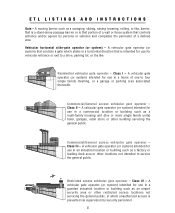
... like , barrier, that is a stand-alone passage barrier or is prevented via supervision by persons or vehicles and completes the perimeter of one-to service the general public. A vehicular gate operator (or system) intended for use in an industrial location or building such as a multi-family housing unit (five or more single...
... like , barrier, that is a stand-alone passage barrier or is prevented via supervision by persons or vehicles and completes the perimeter of one-to service the general public. A vehicular gate operator (or system) intended for use in an industrial location or building such as a multi-family housing unit (five or more single...
MIRACLE ONE Manual
Page 7
...industry standards. • Confirm that all appropriate features and accessory devices are being incorporated, including both sides of the gate to warn persons in the sliding gate below a 4 foot height that includes a routine re-testing of the entire system including the entrapment protection devices, ...8226; Conspicuously display all features for the owners to insure that this testing is in the open position. • Install the gate operator according to the manufacturer's installation instructions. • Adjust the operator clutch or load-sensing device to the minimum force setting ...
...industry standards. • Confirm that all appropriate features and accessory devices are being incorporated, including both sides of the gate to warn persons in the sliding gate below a 4 foot height that includes a routine re-testing of the entire system including the entrapment protection devices, ...8226; Conspicuously display all features for the owners to insure that this testing is in the open position. • Install the gate operator according to the manufacturer's installation instructions. • Adjust the operator clutch or load-sensing device to the minimum force setting ...
MIRACLE ONE Manual
Page 8
...8226; Pinch Points Hazard - Body parts may have arms that warning signs are prominently displayed on both sides of pedestrians before operating the gate. Be sure that can overlap with exposed rollers or openings large enough to allow anyone to move , which can result in serious injury.... The opening . SWING GATE SYSTEMS • Entrapment Zone Hazard - Pedestrians must stay clear of the opening mechanism at all obstructions clear of the vicinity of the ...
...8226; Pinch Points Hazard - Body parts may have arms that warning signs are prominently displayed on both sides of pedestrians before operating the gate. Be sure that can overlap with exposed rollers or openings large enough to allow anyone to move , which can result in serious injury.... The opening . SWING GATE SYSTEMS • Entrapment Zone Hazard - Pedestrians must stay clear of the opening mechanism at all obstructions clear of the vicinity of the ...
MIRACLE ONE Manual
Page 9
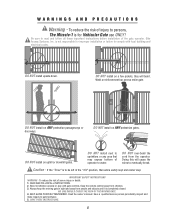
...or play with local building and electrical codes. NO ONE SHOULD CROSS THE PATH OF THE MOVING GATE. 4. Read the owner's manual. is not responsible for improper installation or failure to persons, The Miracle-1 is for Vehicular Gate use ONLY! DO NOT install on ANY pedestrian passageways ...or doorways. Doing this will bend. Caution - READ AND FOLLOW ALL INSTRUCTIONS. 2. Weld a reinforcement bar across entire gate. DO NOT over-bend the cord from ...
...or play with local building and electrical codes. NO ONE SHOULD CROSS THE PATH OF THE MOVING GATE. 4. Read the owner's manual. is not responsible for improper installation or failure to persons, The Miracle-1 is for Vehicular Gate use ONLY! DO NOT install on ANY pedestrian passageways ...or doorways. Doing this will bend. Caution - READ AND FOLLOW ALL INSTRUCTIONS. 2. Weld a reinforcement bar across entire gate. DO NOT over-bend the cord from ...
MIRACLE ONE Manual
Page 10
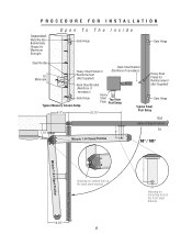
... Steel Bracket (Not Supplied) (Reinforce if necessary) Heavy Gate Hinge Typical Masonry Column Setup Steel Top View Plate Post Setup Gate Hinge Typical Steel 8.5" 25.75" Post Setup Out Gate in Closed Position 7.75" 6" In Miracle 1 in Closed Position 90° / 105° Gate in Open Position Miracle 1 in Open Position Indexing on central hole in...
... Steel Bracket (Not Supplied) (Reinforce if necessary) Heavy Gate Hinge Typical Masonry Column Setup Steel Top View Plate Post Setup Gate Hinge Typical Steel 8.5" 25.75" Post Setup Out Gate in Closed Position 7.75" 6" In Miracle 1 in Closed Position 90° / 105° Gate in Open Position Miracle 1 in Open Position Indexing on central hole in...
MIRACLE ONE Manual
Page 11
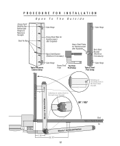
...Bracket (Reinforce if necessary) Typical Masonry Column Setup Gate Hinge Heavy Steel Top View Plate Post Setup Gate Hinge Typical Steel Post Setup 6" Indexing on mounting hole in the front steel bracket. 6" 90° / 105° Gate in Open Position Miracle 1 in Open Position 8.5" This Plate Not ...Supplied 7.75" Out Gate in Closed Position In Miracle 1 in the back ...
...Bracket (Reinforce if necessary) Typical Masonry Column Setup Gate Hinge Heavy Steel Top View Plate Post Setup Gate Hinge Typical Steel Post Setup 6" Indexing on mounting hole in the front steel bracket. 6" 90° / 105° Gate in Open Position Miracle 1 in Open Position 8.5" This Plate Not ...Supplied 7.75" Out Gate in Closed Position In Miracle 1 in the back ...
MIRACLE ONE Manual
Page 12
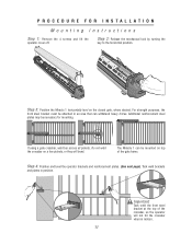
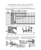
... crossbar, so the operator will bend. Step 4: Position and level the operator brackets and reinforcement plates. (See next page). Step 3: Position the Miracle 1 horizontally level on a few pickets, or they will not hit the crossbar when in position. Do not weld the crossbar on the closed... gate, where desired. Important: Tack weld the front steel bracket at the top of the gate frame. The Miracle 1 can withstand heavy forces. For strength purposes, the front steel bracket must be attached in...
... crossbar, so the operator will bend. Step 4: Position and level the operator brackets and reinforcement plates. (See next page). Step 3: Position the Miracle 1 horizontally level on a few pickets, or they will not hit the crossbar when in position. Do not weld the crossbar on the closed... gate, where desired. Important: Tack weld the front steel bracket at the top of the gate frame. The Miracle 1 can withstand heavy forces. For strength purposes, the front steel bracket must be attached in...
MIRACLE ONE Manual
Page 13
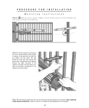
.... Make sure the operator is finished, remove the operator! Secure operator with the washer and nut (See Below). Secure operator to the gate may damage the operator. Important: These nuts MUST be tight or unit will be placed between traveler carriage and TOP of front bracket. Caution... Step 6 Refer to Step 7 2.25" Vertical Height Difference Step 5: With the operator removed, completely weld around the brackets and plates on the gate. Step 6: Remove the nut, bolt and bushing from the traveler carriage at the front of the steel bracket that will not work correctly! Place...
.... Make sure the operator is finished, remove the operator! Secure operator with the washer and nut (See Below). Secure operator to the gate may damage the operator. Important: These nuts MUST be tight or unit will be placed between traveler carriage and TOP of front bracket. Caution... Step 6 Refer to Step 7 2.25" Vertical Height Difference Step 5: With the operator removed, completely weld around the brackets and plates on the gate. Step 6: Remove the nut, bolt and bushing from the traveler carriage at the front of the steel bracket that will not work correctly! Place...
MIRACLE ONE Manual
Page 14
...to the operator and control board. Step 9: Lock the operator by turning the key to complete the final adjustments on the gate until you hear the key release click into place. Completing this successfully finishes the basic mounting of the operator to fail prematurely.... An off-level installation may cause the gate or operator to the gate. Step 10: The following pages show the correct electrical procedures needed for the operator. PROCEDURE FOR INSTALLATION Mounting Instructions ...
...to the operator and control board. Step 9: Lock the operator by turning the key to complete the final adjustments on the gate until you hear the key release click into place. Completing this successfully finishes the basic mounting of the operator to fail prematurely.... An off-level installation may cause the gate or operator to the gate. Step 10: The following pages show the correct electrical procedures needed for the operator. PROCEDURE FOR INSTALLATION Mounting Instructions ...
MIRACLE ONE Manual
Page 15
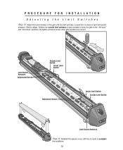
... are correct. PROCEDURE FOR INSTALLATION Adjusting the Limit Switches Step 11: Adjust the travel distance of the gate with the 4 screws to complete the installation. 14 Slide to stop the gate in the "full open" and "full closed" positions. Limit Switch Armature Adjustment Screws Outside Limit Switch Inside Limit Switch Adjustment Screws...
... are correct. PROCEDURE FOR INSTALLATION Adjusting the Limit Switches Step 11: Adjust the travel distance of the gate with the 4 screws to complete the installation. 14 Slide to stop the gate in the "full open" and "full closed" positions. Limit Switch Armature Adjustment Screws Outside Limit Switch Inside Limit Switch Adjustment Screws...
MIRACLE ONE Manual
Page 19
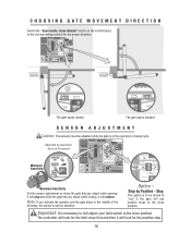
... reverse. Adjusted by Positive - Stop by Qualified Service Personnel Minimum Sensitivity Maximum Sensitivity Set the sensor adjustment so when the gate hits any object while opening or closing , it will look for the limit close first and then it will use positive stops at the...: It is to still adjust your limit switch at the close position. The controller will look for the proper direction. 8 8 The gate opens inward. Note: If you activate the operator and the gate stops in the opening , it will stop . 18 Stop This option is necessary to be adjusted while the...
... reverse. Adjusted by Positive - Stop by Qualified Service Personnel Minimum Sensitivity Maximum Sensitivity Set the sensor adjustment so when the gate hits any object while opening or closing , it will look for the limit close first and then it will use positive stops at the...: It is to still adjust your limit switch at the close position. The controller will look for the proper direction. 8 8 The gate opens inward. Note: If you activate the operator and the gate stops in the opening , it will stop . 18 Stop This option is necessary to be adjusted while the...
MIRACLE ONE Manual
Page 20
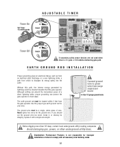
...whole piece of a direct lightning strike, proper grounding can absorb the tremendous power of wire. Chamberlain Professional Products is ON, gate will hit vehicle obstructing gate path. EARTH GROUND ROD INSTALLATION Proper grounding gives an electrical charge, such as from an electrical static discharge or a near lightning... for the ground wire. Without this path, the intense energy generated by lightning could be directed towards the Elite gate operator. Timer On Set Timer 1 to dissipate its integrity, replace it with all necessary local building codes. 19 Although nothing...
...whole piece of a direct lightning strike, proper grounding can absorb the tremendous power of wire. Chamberlain Professional Products is ON, gate will hit vehicle obstructing gate path. EARTH GROUND ROD INSTALLATION Proper grounding gives an electrical charge, such as from an electrical static discharge or a near lightning... for the ground wire. Without this path, the intense energy generated by lightning could be directed towards the Elite gate operator. Timer On Set Timer 1 to dissipate its integrity, replace it with all necessary local building codes. 19 Although nothing...
MIRACLE ONE Manual
Page 22
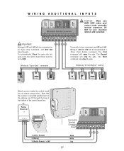
...789 HELP 0 REV A Elite Entry Phone Card Reader Digital Lock Push Button Key Switch Card Reader Digital Lock Mount receiver inside removable terminal connectors. MIRACLE SURGE PROTECTION Important: Wiring at #21 and #22 will be turned ON. 21 22 23 24 ® LAKE FOREST, CALIFORNIA www.eliteaccess....com Works as "Open Only" command To provide a close command use #23 and #24. To automatically Close the gate after an open the gate. Wiring at the bottom of the control board box. DO NOT let wire insulation interfere with connection. BLACK WHITE RED BROWN BLUE ...
...789 HELP 0 REV A Elite Entry Phone Card Reader Digital Lock Push Button Key Switch Card Reader Digital Lock Mount receiver inside removable terminal connectors. MIRACLE SURGE PROTECTION Important: Wiring at #21 and #22 will be turned ON. 21 22 23 24 ® LAKE FOREST, CALIFORNIA www.eliteaccess....com Works as "Open Only" command To provide a close command use #23 and #24. To automatically Close the gate after an open the gate. Wiring at the bottom of the control board box. DO NOT let wire insulation interfere with connection. BLACK WHITE RED BROWN BLUE ...

MIRACLE ONE Manual
Page 23
...to scale Exit Loop Inside H Safety Loop F I which ever is for a typical single Miracle 1 loop installation. Exit Loop H = G or I G E Distance from open gate Center Loop B Outside D C Safety Loop A End of 4 feet away from open gate Outside Safety Loop: If A = Then C = 6 Feet 4 Feet 9 Feet 4.5 ... Feet Center Loop: This loop must have enough separation between loop and gate when opened or closed. Individual circumstances may alter dimensions. Caution: Distance "E" must be a minimum of open gate! For toll free technical support: 1-888-ELITE-10 22 If driveway ...
...to scale Exit Loop Inside H Safety Loop F I which ever is for a typical single Miracle 1 loop installation. Exit Loop H = G or I G E Distance from open gate Center Loop B Outside D C Safety Loop A End of 4 feet away from open gate Outside Safety Loop: If A = Then C = 6 Feet 4 Feet 9 Feet 4.5 ... Feet Center Loop: This loop must have enough separation between loop and gate when opened or closed. Individual circumstances may alter dimensions. Caution: Distance "E" must be a minimum of open gate! For toll free technical support: 1-888-ELITE-10 22 If driveway ...

MIRACLE ONE Manual
Page 24
... is smaller than 18 ft, then D must be 4.5 ft If driveway is bigger than 18 ft, then D must be a minimum of open gate B E Distance from open gate Out In Exit Loop Inside H Safety F Loop Center Loop Outside D C Safety A Loop I which ever is for a typical master/slave loop ...installation. Exit Loop H = G or I Outside Safety Loop: If A = Then C = 6 Feet 4 Feet G End of 4 feet away from open gate 9 Feet 4.5 Feet 12 Feet 5 Feet 15 Feet 5 Feet 18 Feet 5.5 Feet 21 Feet 6 Feet Center Loop: This loop must be 5 ft If B = Then E = 6 Feet...
... is smaller than 18 ft, then D must be 4.5 ft If driveway is bigger than 18 ft, then D must be a minimum of open gate B E Distance from open gate Out In Exit Loop Inside H Safety F Loop Center Loop Outside D C Safety A Loop I which ever is for a typical master/slave loop ...installation. Exit Loop H = G or I Outside Safety Loop: If A = Then C = 6 Feet 4 Feet G End of 4 feet away from open gate 9 Feet 4.5 Feet 12 Feet 5 Feet 15 Feet 5 Feet 18 Feet 5.5 Feet 21 Feet 6 Feet Center Loop: This loop must be 5 ft If B = Then E = 6 Feet...

MIRACLE ONE Manual
Page 26
... VAC INPUT Removable Terminal Connectors 17 18 19 20 21 22 23 24 25 26 27 Surge Suppressor Elite Part # A 24 Com N.O. Center Loop Allows gate to stay open when vehicles are obstructing gate path. Gnd +24V 23 25 Elite Part # A 24 17 18 Com N.O. LOOP DETECTOR WIRING Safety Loop Allows...
... VAC INPUT Removable Terminal Connectors 17 18 19 20 21 22 23 24 25 26 27 Surge Suppressor Elite Part # A 24 Com N.O. Center Loop Allows gate to stay open when vehicles are obstructing gate path. Gnd +24V 23 25 Elite Part # A 24 17 18 Com N.O. LOOP DETECTOR WIRING Safety Loop Allows...


