MATDCBB Green Control Board V.6.4 or newer Manual
Page 2
...SAMS) SAMS With Other Operators 17 SAMS Two Mega Arms with "Memory 17 CONTROL BOARD LAYOUT Input Locations 18 MEGA ARM UL PARTS LIST Part Numbers and Descriptions 19 Parts Shipped 19 Mega Arm Tower Unique Parts List 19 Mega Arm Options Parts List 19 ACCESSORIES 20 OPERATOR NOTES 21... Overview 3 UL325 MODEL CLASSIFICATIONS 4 SAFETY INSTALLATION INFORMATION 5 INSTALLATION Concrete Pad 6 Anchors 6 Conduits 6 Dimensions 6 WIRING AND HOOKUP AC Power Hookup (120/230 Vac 7 Input Commands 1-8 7 Accessory and Relay Connections 8 Battery Installation 8 Master/Second Wiring 8 REVERSING...
...SAMS) SAMS With Other Operators 17 SAMS Two Mega Arms with "Memory 17 CONTROL BOARD LAYOUT Input Locations 18 MEGA ARM UL PARTS LIST Part Numbers and Descriptions 19 Parts Shipped 19 Mega Arm Tower Unique Parts List 19 Mega Arm Options Parts List 19 ACCESSORIES 20 OPERATOR NOTES 21... Overview 3 UL325 MODEL CLASSIFICATIONS 4 SAFETY INSTALLATION INFORMATION 5 INSTALLATION Concrete Pad 6 Anchors 6 Conduits 6 Dimensions 6 WIRING AND HOOKUP AC Power Hookup (120/230 Vac 7 Input Commands 1-8 7 Accessory and Relay Connections 8 Battery Installation 8 Master/Second Wiring 8 REVERSING...

MATDCBB Green Control Board V.6.4 or newer Manual
Page 3
...• Small Screwdriver • T25 Torx Head Screwdriver AVERTISSEMENT UNIT OVERVIEAAWAVVTEETRRETTNIISSTSSIOEENMMEENNTT The LiftMaster model MEGA ARM barrier style parking gate operator is unique in open and close travel if tail...are many parts that might otherwise fail. • State of being powered from electric shock. AVERTISSEMENT • Direct drive gear reducer eliminates ...; Molded Polyethylene UV stabilized cover never needs wax or paint (excludes towers). INTRODUCTION WARNING Mechanical CWWAAUARTRINNOIINNNGG Electrical CAWUATRIONNING When you see this manual and...
...• Small Screwdriver • T25 Torx Head Screwdriver AVERTISSEMENT UNIT OVERVIEAAWAVVTEETRRETTNIISSTSSIOEENMMEENNTT The LiftMaster model MEGA ARM barrier style parking gate operator is unique in open and close travel if tail...are many parts that might otherwise fail. • State of being powered from electric shock. AVERTISSEMENT • Direct drive gear reducer eliminates ...; Molded Polyethylene UV stabilized cover never needs wax or paint (excludes towers). INTRODUCTION WARNING Mechanical CWWAAUARTRINNOIINNNGG Electrical CAWUATRIONNING When you see this manual and...
MATDCBB Green Control Board V.6.4 or newer Manual
Page 6
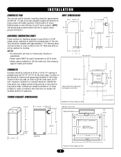
...5-1/2" 2" Center Line These Dimensions Will Center the Operator on the Pad 3-1/2" 3-1/2" Inside Post 5-1/2" 8" 9" TOWER CABINET DIMENSIONS 12" Pedestal Foot Print of Base on Pad 6" 3-1/4" 13-1/2" 3-1/2" Pad (24" x 24" x 24") Gate Arm Bracket 7-1/8" 7-1/8" 3-1/2" 42" 10-1/4" 42" 36-1/2" 9-7/8" 8-1/4" Open Area In Base For Conduit 13-1/2" 14...showing above concrete surface in pedestal base and 10 1/4" x 8 1/4" for leveling. Pad should be 120/230 Vac main power, low voltage control wiring and one is 30°or below frost line in order to get the most reach out of ...
...5-1/2" 2" Center Line These Dimensions Will Center the Operator on the Pad 3-1/2" 3-1/2" Inside Post 5-1/2" 8" 9" TOWER CABINET DIMENSIONS 12" Pedestal Foot Print of Base on Pad 6" 3-1/4" 13-1/2" 3-1/2" Pad (24" x 24" x 24") Gate Arm Bracket 7-1/8" 7-1/8" 3-1/2" 42" 10-1/4" 42" 36-1/2" 9-7/8" 8-1/4" Open Area In Base For Conduit 13-1/2" 14...showing above concrete surface in pedestal base and 10 1/4" x 8 1/4" for leveling. Pad should be 120/230 Vac main power, low voltage control wiring and one is 30°or below frost line in order to get the most reach out of ...
MATDCBB Green Control Board V.6.4 or newer Manual
Page 7
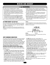
...not used as a safety-stop in the same lane. car "backs-away" from devices connected 6, CLOSE: When used to activate above inputs. power switch. Connect the batteries after input is NCIA ADVERTENCIA connections to the appropriate points for the desired operation, see page 18. 9, 10, 11,12... not connect any wiring or attempt to run in chassis to avoid chafing. NOTE: Above inputs are the commons (0 Vdc) to be used with the MEGA ARM. Connect the the conduit or pedestal post. NG W I R I N WG AARNNDINHGO O K U P WARNING To reduce the risk of SEVERE INJURY or DEATH: ...
...not used as a safety-stop in the same lane. car "backs-away" from devices connected 6, CLOSE: When used to activate above inputs. power switch. Connect the batteries after input is NCIA ADVERTENCIA connections to the appropriate points for the desired operation, see page 18. 9, 10, 11,12... not connect any wiring or attempt to run in chassis to avoid chafing. NOTE: Above inputs are the commons (0 Vdc) to be used with the MEGA ARM. Connect the the conduit or pedestal post. NG W I R I N WG AARNNDINHGO O K U P WARNING To reduce the risk of SEVERE INJURY or DEATH: ...
MATDCBB Green Control Board V.6.4 or newer Manual
Page 8
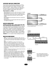
... option) and fires relay when a tail-gate is not already in place (Figure 1). (Use LiftMaster MBAT or 29-NP712 for replacement batteries.) Replace in it). ALWAYS HOOKUP AND TURN ON AC POWER BEFORE INSTALLING BATTERIES. Connect red lead from operator to the positive (RED +) terminal of one is...pushed up off , relay will only pulse when input is 0 Vdc (-). S1-6 off , relay will pulse relay when arm reaches full open and close loop - After turning on AC power, install two new, fully charged 12 volt DC batteries on both gates. Place the supplied jumper between gates (Figure 2)....
... option) and fires relay when a tail-gate is not already in place (Figure 1). (Use LiftMaster MBAT or 29-NP712 for replacement batteries.) Replace in it). ALWAYS HOOKUP AND TURN ON AC POWER BEFORE INSTALLING BATTERIES. Connect red lead from operator to the positive (RED +) terminal of one is...pushed up off , relay will only pulse when input is 0 Vdc (-). S1-6 off , relay will pulse relay when arm reaches full open and close loop - After turning on AC power, install two new, fully charged 12 volt DC batteries on both gates. Place the supplied jumper between gates (Figure 2)....
MATDCBB Green Control Board V.6.4 or newer Manual
Page 9
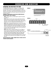
...traffic flow direction (Figure 1). Next, turn on the control board must be (J4-7) orange then (J4-8) blue (Figure 2). WARNING: POWER MUST BE OFF AND NO ARM INSTALLED BEFORE MAKING THESE CHANGES. STEP 4: Now check to make sure that S1 #7 is on (Figure 1), motor wires are reversed, ...of movement in relation to the unit's normal operation. Cam Arm Output Shaft of arm. REVERSING ARM DIRECTION REVERSING THE DIRECTION OF THE ARM The MEGA ARM allows for mounting in tight places or when it is set to close. STEP 1: Before power up to enable reverse of Gear Box 9 STEP 2: Next,...
...traffic flow direction (Figure 1). Next, turn on the control board must be (J4-7) orange then (J4-8) blue (Figure 2). WARNING: POWER MUST BE OFF AND NO ARM INSTALLED BEFORE MAKING THESE CHANGES. STEP 4: Now check to make sure that S1 #7 is on (Figure 1), motor wires are reversed, ...of movement in relation to the unit's normal operation. Cam Arm Output Shaft of arm. REVERSING ARM DIRECTION REVERSING THE DIRECTION OF THE ARM The MEGA ARM allows for mounting in tight places or when it is set to close. STEP 1: Before power up to enable reverse of Gear Box 9 STEP 2: Next,...
MATDCBB Green Control Board V.6.4 or newer Manual
Page 10
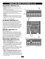
... Switch in turned on S1-6 & S2-7, gate will keep the gate up . SWITCH PACK S2 (6-8) SWITCH 6 - AUTO OPEN ON POWER FAILURE: When switch number 8 is restored the operator will close by loop, not by timer when all switches off . Once...1A DC C8 C2Ø + R15 D1 + F4 R2 R11 B1 HBEAT BAT LO AC POWER K1 D11 D12 D14 F3 WARNING FOR R62 CONTINUOUS PROTECTION AGAINST FIRE DX1 REPLACE ONLY WITH THE...will pulse K1 relay when OPEN LIMIT (OLS) is OFF. On the MEGA ARM the switches 1-5 on J5. SWITCH 7 - AUTO CLOSE TIMER: Default is reached (activates a swing or slide gate its lane).
... Switch in turned on S1-6 & S2-7, gate will keep the gate up . SWITCH PACK S2 (6-8) SWITCH 6 - AUTO OPEN ON POWER FAILURE: When switch number 8 is restored the operator will close by loop, not by timer when all switches off . Once...1A DC C8 C2Ø + R15 D1 + F4 R2 R11 B1 HBEAT BAT LO AC POWER K1 D11 D12 D14 F3 WARNING FOR R62 CONTINUOUS PROTECTION AGAINST FIRE DX1 REPLACE ONLY WITH THE...will pulse K1 relay when OPEN LIMIT (OLS) is OFF. On the MEGA ARM the switches 1-5 on J5. SWITCH 7 - AUTO CLOSE TIMER: Default is reached (activates a swing or slide gate its lane).
MATDCBB Green Control Board V.6.4 or newer Manual
Page 11
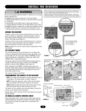
... AVERTISSEMENT Contacts 1 and 2 on the J5 terminal strip at the AVERTISSEMENT bottom of the logic board (Figure 1). The power terminals are FIGURE 3 now erased. PT4R B2 Security Mode Terminals Jumper Security Mode Terminals Jumper PROGRAMMING TAHEDRVEMEOTRE TTOETNHECREIACEIVER STEP 1: ...control transmitters. • Activate gate or door ONLY when it can be erased. F3 MOV 1 10 TYPE AND RATING OF1FUSE 2 3 MOT4OR D26 D25 - Re-connect power to Comply with a coin or a screwdriver. WARNINIGN S T A L L T H E R E C E I V E R WARNING To prevent possible SERIOUS ...
... AVERTISSEMENT Contacts 1 and 2 on the J5 terminal strip at the AVERTISSEMENT bottom of the logic board (Figure 1). The power terminals are FIGURE 3 now erased. PT4R B2 Security Mode Terminals Jumper Security Mode Terminals Jumper PROGRAMMING TAHEDRVEMEOTRE TTOETNHECREIACEIVER STEP 1: ...control transmitters. • Activate gate or door ONLY when it can be erased. F3 MOV 1 10 TYPE AND RATING OF1FUSE 2 3 MOT4OR D26 D25 - Re-connect power to Comply with a coin or a screwdriver. WARNINIGN S T A L L T H E R E C E I V E R WARNING To prevent possible SERIOUS ...
MATDCBB Green Control Board V.6.4 or newer Manual
Page 12
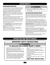
... bracket. ALL maintenance MUST be needed so that you have programmed the unit to be sure proper the cam arm which can be done by a LiftMaster professional. 10. Insert the bolts through the bracket. position, time out (using the same delay set at S-2. ...reverses when obstructed. READ AND FOLLOW ALL INSTRUCTIONS. 2. NOTE: To prevent entrapment, allow sensitivity CAUTION • Disconnect power BEFORE performing ANY adjustments near proper arm 1-5) and then close the gate while adjusting until a WARNING required, refer to adjust and retest the gate operator...
... bracket. ALL maintenance MUST be needed so that you have programmed the unit to be sure proper the cam arm which can be done by a LiftMaster professional. 10. Insert the bolts through the bracket. position, time out (using the same delay set at S-2. ...reverses when obstructed. READ AND FOLLOW ALL INSTRUCTIONS. 2. NOTE: To prevent entrapment, allow sensitivity CAUTION • Disconnect power BEFORE performing ANY adjustments near proper arm 1-5) and then close the gate while adjusting until a WARNING required, refer to adjust and retest the gate operator...
MATDCBB Green Control Board V.6.4 or newer Manual
Page 13
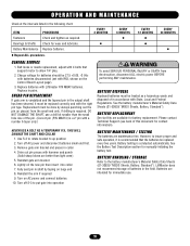
...(see back of batteries in shaft by always punching out the pin (or pieces) from electrocution, disconnect ALL electric power BEFORE performing ANY maintenance. AVERTISSEMENT BATTERY MAINTENANCE / TESTING The batteries are available for contact information). Use S-3 to rotate... ADVERTENCIA ADVERTENCIA PRECAUCIÓN ADVERTENCIA 13 Replacement must be 27.5 +0.05, -0 Vdc with batteries disconnected (set with Liftmaster P/N MBAT batteries. Reinstall the arm if required 9. BATTERY HANDLING / STORAGE Refer to up position 2. Belt loose or needs replacement, adjust with the ...
...(see back of batteries in shaft by always punching out the pin (or pieces) from electrocution, disconnect ALL electric power BEFORE performing ANY maintenance. AVERTISSEMENT BATTERY MAINTENANCE / TESTING The batteries are available for contact information). Use S-3 to rotate... ADVERTENCIA ADVERTENCIA PRECAUCIÓN ADVERTENCIA 13 Replacement must be 27.5 +0.05, -0 Vdc with batteries disconnected (set with Liftmaster P/N MBAT batteries. Reinstall the arm if required 9. BATTERY HANDLING / STORAGE Refer to up position 2. Belt loose or needs replacement, adjust with the ...
MATDCBB Green Control Board V.6.4 or newer Manual
Page 14
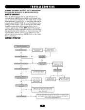
... on AC fail) on ? Yes No Yes Yes Is the HBEAT flashing now? No Check fuse F3, Replace if blown. Remove AC and battery power Yes then reapply to function properly. If LED 12 comes ON, batteries are correct. 14 Correct charge voltage is approximately 24.5Vdc. Is the "BAT...voltage is 27.5 Vdc with batteries not connected (set with R63, shown on S2 is not binding, then adjust the IRD. DISCONNECT BATTERIES AND AC POWER BEFORE SERVICING ANY MECHANICAL OR MOVING COMPONENTS. Yes No Is the Safety, Backaway, or Open input active? NOTE: If LED D12 does light, gate...
... on AC fail) on ? Yes No Yes Yes Is the HBEAT flashing now? No Check fuse F3, Replace if blown. Remove AC and battery power Yes then reapply to function properly. If LED 12 comes ON, batteries are correct. 14 Correct charge voltage is approximately 24.5Vdc. Is the "BAT...voltage is 27.5 Vdc with batteries not connected (set with R63, shown on S2 is not binding, then adjust the IRD. DISCONNECT BATTERIES AND AC POWER BEFORE SERVICING ANY MECHANICAL OR MOVING COMPONENTS. Yes No Is the Safety, Backaway, or Open input active? NOTE: If LED D12 does light, gate...
MATDCBB Green Control Board V.6.4 or newer Manual
Page 16
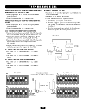
...Trap Close Loop Close Loop ON ON ON ON ON ON ON OFF 12345678 Close Loop Trap S2 Card Reader Tele-entry Radio Control Mega Arm Trap Mega Arm ON ON ON ON ON ON ON OFF OFF 12345678 16 Press the connector into the J1 connector pins. TRAP INSTRUCTIONS INSTALL THE ...K1 AUXILIARY RELAY AND CONNECTOR AT MEGA ARM CONNECTED TO THE ACCESS DEVICE 1. Reconnect the DC power by replacing the neutral (Black) wire to 00100001 where 1 is up and 0 is open output (NO) of inputs: a. Connect...
...Trap Close Loop Close Loop ON ON ON ON ON ON ON OFF 12345678 Close Loop Trap S2 Card Reader Tele-entry Radio Control Mega Arm Trap Mega Arm ON ON ON ON ON ON ON OFF OFF 12345678 16 Press the connector into the J1 connector pins. TRAP INSTRUCTIONS INSTALL THE ...K1 AUXILIARY RELAY AND CONNECTOR AT MEGA ARM CONNECTED TO THE ACCESS DEVICE 1. Reconnect the DC power by replacing the neutral (Black) wire to 00100001 where 1 is up and 0 is open output (NO) of inputs: a. Connect...
MATDCBB Green Control Board V.6.4 or newer Manual
Page 18
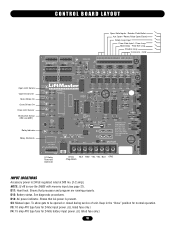
...and program are running properly. S3: Manual open. F3: 10 amp ATO type fuse for 24Vac input power. (UL listed fuse only.) F4: 15 amp ATO type fuse for normal operation. MOV MOTOR Aux Relay...Loop Back Away - BAT+ 24VAC XFMR MOTOR 24Vdc BLK RED YEL YEL BLU ORG (Regulated) INPUT LOCATIONS Accessory power is present. Reader, Push Button Aux Open / Reset (Pulse Open/Close) Safety Loop Input Close Gate Input...1A DC C8 C2Ø + R15 D1 + F4 R2 R11 B1 HBEAT BAT LO AC POWER K1 D11 D12 D14 F3 WARNING FOR R62 CONTINUOUS PROTECTION AGAINST FIRE DX1 REPLACE ONLY WITH THE SAME...
...and program are running properly. S3: Manual open. F3: 10 amp ATO type fuse for 24Vac input power. (UL listed fuse only.) F4: 15 amp ATO type fuse for normal operation. MOV MOTOR Aux Relay...Loop Back Away - BAT+ 24VAC XFMR MOTOR 24Vdc BLK RED YEL YEL BLU ORG (Regulated) INPUT LOCATIONS Accessory power is present. Reader, Push Button Aux Open / Reset (Pulse Open/Close) Safety Loop Input Close Gate Input...1A DC C8 C2Ø + R15 D1 + F4 R2 R11 B1 HBEAT BAT LO AC POWER K1 D11 D12 D14 F3 WARNING FOR R62 CONTINUOUS PROTECTION AGAINST FIRE DX1 REPLACE ONLY WITH THE SAME...

MATDCBB Green Control Board V.6.4 or newer Manual
Page 23
... UNIT. IN ORDER TO INSTALL AND USE THE MEGA ARM, YOU MUST UNDERSTAND AND BE IN FULL UNCONDITIONAL AGREEMENT WITH ALL STIPULATIONS OUTLINED ABOVE. WARRANTY REGISTRATION MAIL OR FAX THIS PORTION TO LIFTMASTER TO CONFIRM YOUR WARRANTY NAME OF INSTALLING DEALER NAME...God (lightning, floods, insect damage, etc.), power surges, units subjected to corrosive environments, incorrect installation or application, the batteries or incorrect battery installation, operation without notice. LiftMaster reserves the right of final determination as to LiftMaster within the warranty period, shall at any ...
... UNIT. IN ORDER TO INSTALL AND USE THE MEGA ARM, YOU MUST UNDERSTAND AND BE IN FULL UNCONDITIONAL AGREEMENT WITH ALL STIPULATIONS OUTLINED ABOVE. WARRANTY REGISTRATION MAIL OR FAX THIS PORTION TO LIFTMASTER TO CONFIRM YOUR WARRANTY NAME OF INSTALLING DEALER NAME...God (lightning, floods, insect damage, etc.), power surges, units subjected to corrosive environments, incorrect installation or application, the batteries or incorrect battery installation, operation without notice. LiftMaster reserves the right of final determination as to LiftMaster within the warranty period, shall at any ...


