
LJ8950W Manual
Page 1
Light-Duty Jackshaft Operator for Rolling Doors Model LJ8950W For Light Duty Commercial Use Install On Rolling Doors Only NOT FOR RESIDENTIAL USE After Installation, Please Leave with sectional type doors. Register your door operator to receive updates and offers from LiftMaster SM Take a photo of door operation ...to ensure safe operation. • The model number is to 71403 (US) or visit www.liftmaster.photo (Global) 2 YEAR WARRANTY LiftMaster 300 Windsor Drive Oak Brook, IL 60523 Send it in by texting the photo to be installed and serviced by a trained door systems technician only.
Light-Duty Jackshaft Operator for Rolling Doors Model LJ8950W For Light Duty Commercial Use Install On Rolling Doors Only NOT FOR RESIDENTIAL USE After Installation, Please Leave with sectional type doors. Register your door operator to receive updates and offers from LiftMaster SM Take a photo of door operation ...to ensure safe operation. • The model number is to 71403 (US) or visit www.liftmaster.photo (Global) 2 YEAR WARRANTY LiftMaster 300 Windsor Drive Oak Brook, IL 60523 Send it in by texting the photo to be installed and serviced by a trained door systems technician only.
LJ8950W Manual
Page 2
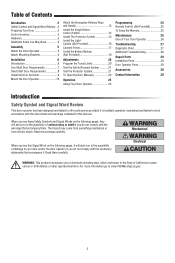
... are known to the State of Your Door Operator 26 Troubleshooting 27 Diagnostic Chart 27 Additional Troubleshooting 28 Repair Parts 29 Installation Parts 29 Door Operator Parts 29 Accessories 30 Contact Information 30 Introduction Safety Symbol and Signal Word Review This door operator ...has been designed and tested to offer safe service provided it is installed, operated, maintained and tested in strict accordance with the instructions and warnings contained in this Signal Word on the following pages,...
... are known to the State of Your Door Operator 26 Troubleshooting 27 Diagnostic Chart 27 Additional Troubleshooting 28 Repair Parts 29 Installation Parts 29 Door Operator Parts 29 Accessories 30 Contact Information 30 Introduction Safety Symbol and Signal Word Review This door operator ...has been designed and tested to offer safe service provided it is installed, operated, maintained and tested in strict accordance with the instructions and warnings contained in this Signal Word on the following pages,...
LJ8950W Manual
Page 3
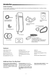
...NOT run operator if the door is exposed lower than 650 lbs. To prevent damage to door and operator: • ALWAYS disable locks BEFORE installing and operating the operator. • ONLY operate door operator at 120V, 60 Hz to avoid malfunction and damage. • DO NOT exceed...ALL locks and remove ALL ropes connected to door BEFORE installing and operating door operator to avoid entanglement. • DO NOT install operator below 8 ft. (2.5 m), a chain guard must be installed where the drive chain is locked. • Chain guard to be installed to exceed 168 sq./ft.) 3 If your door...
...NOT run operator if the door is exposed lower than 650 lbs. To prevent damage to door and operator: • ALWAYS disable locks BEFORE installing and operating the operator. • ONLY operate door operator at 120V, 60 Hz to avoid malfunction and damage. • DO NOT exceed...ALL locks and remove ALL ropes connected to door BEFORE installing and operating door operator to avoid entanglement. • DO NOT install operator below 8 ft. (2.5 m), a chain guard must be installed where the drive chain is locked. • Chain guard to be installed to exceed 168 sq./ft.) 3 If your door...
LJ8950W Manual
Page 4
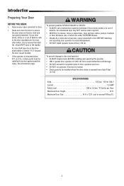
If anything is packaged in one carton which contains the motor unit and the parts illustrated below. Battery Backup (Model 485LM): Provides backup power to install the safety reversing sensor. Fastening hardware: Alternate floor mounting of the safety reversing sensor will require hardware not provided. 90˚ connector for cable ...
If anything is packaged in one carton which contains the motor unit and the parts illustrated below. Battery Backup (Model 485LM): Provides backup power to install the safety reversing sensor. Fastening hardware: Alternate floor mounting of the safety reversing sensor will require hardware not provided. 90˚ connector for cable ...
LJ8950W Manual
Page 5
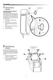
Assembly 1 Attach the Drive Sprocket The door operator can be installed on either side of the operator. 2. Insert bolts into the motor shaft. 2. Position two mounting brackets on each side of the door. Hand tighten the ...bolts. Fasten the mounting brackets to the wall with the door sprocket. 1. The drive sprocket can be installed on your installation. Insert the drive sprocket into the motor shaft and the drive sprocket. 4. Motor Shaft Drive Sprocket Bolt Bolt 2 Attach Mounting Brackets The operator can...
Assembly 1 Attach the Drive Sprocket The door operator can be installed on either side of the operator. 2. Insert bolts into the motor shaft. 2. Position two mounting brackets on each side of the door. Hand tighten the ...bolts. Fasten the mounting brackets to the wall with the door sprocket. 1. The drive sprocket can be installed on your installation. Insert the drive sprocket into the motor shaft and the drive sprocket. 4. Motor Shaft Drive Sprocket Bolt Bolt 2 Attach Mounting Brackets The operator can...
LJ8950W Manual
Page 6
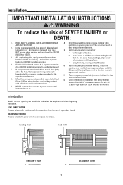
... then exposed moving parts of door. 6. NEVER wear watches, rings or loose clothing while AND INSTRUCTIONS. installing or servicing operator. Install door operator ONLY on the floor. 7. Place emergency release/safety reverse test label in 2. DEAD ...moving parts must a prominent location. Mount the emergency release within sight of 5 3. Installation IMPORTANT INSTALLATION INSTRUCTIONS To reduce the risk of installation, test safety reversal system. Install the Emergency Release Marking. Upon completion of SEVERE INJURY or DEATH: 1. LIVE SHAFT ...
... then exposed moving parts of door. 6. NEVER wear watches, rings or loose clothing while AND INSTRUCTIONS. installing or servicing operator. Install door operator ONLY on the floor. 7. Place emergency release/safety reverse test label in 2. DEAD ...moving parts must a prominent location. Mount the emergency release within sight of 5 3. Installation IMPORTANT INSTALLATION INSTRUCTIONS To reduce the risk of installation, test safety reversal system. Install the Emergency Release Marking. Upon completion of SEVERE INJURY or DEATH: 1. LIVE SHAFT ...
LJ8950W Manual
Page 7
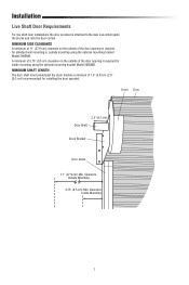
... (9.5 cm) Min. MINIMUM SHAFT LENGTH The door shaft must extend past the drum bracket a minimum of the door opening is required for installing the door sprocket. MINIMUM SIDE CLEARANCE A minimum of 11" (27.9 cm) clearance on the outside mounting using the optional mounting bracket Model 3950MB... door opening is required for inside mounting using the optional mounting bracket Model 3950MB. Clearance Inside Mounting 7 Installation Live Shaft Door Requirements For live shaft door installations the door sprocket is attached to the door axle which spins the drums and rolls the door curtain.
... (9.5 cm) Min. MINIMUM SHAFT LENGTH The door shaft must extend past the drum bracket a minimum of the door opening is required for installing the door sprocket. MINIMUM SIDE CLEARANCE A minimum of 11" (27.9 cm) clearance on the outside mounting using the optional mounting bracket Model 3950MB... door opening is required for inside mounting using the optional mounting bracket Model 3950MB. Clearance Inside Mounting 7 Installation Live Shaft Door Requirements For live shaft door installations the door sprocket is attached to the door axle which spins the drums and rolls the door curtain.
LJ8950W Manual
Page 8
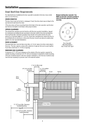
... room in the proper location. If the door brackets interfere with a selection of the door guide is required for door sprocket installation. You MUST use the door sprocket as a template to drill holes in the desired location. Clearance Inside Mounting Door Guide... 8 Installation Dead Shaft Door Requirements For dead shaft door installations the door sprocket is attached to the door drum which align to function correctly. SPRING CLEARANCE The internal door springs ...
... room in the proper location. If the door brackets interfere with a selection of the door guide is required for door sprocket installation. You MUST use the door sprocket as a template to drill holes in the desired location. Clearance Inside Mounting Door Guide... 8 Installation Dead Shaft Door Requirements For dead shaft door installations the door sprocket is attached to the door drum which align to function correctly. SPRING CLEARANCE The internal door springs ...
LJ8950W Manual
Page 9
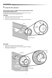
The instructions below describe the general installation procedure. Attach the door sprocket to the door shaft with the through the door shaft. 3. Flange Nut Door Sprocket Drum Drum Tubular Spacer Flat Washer ... regarding your door. Slide the door sprocket onto the end of the door shaft. 2. Slide the door sprocket onto the end of the door shaft. 2. Installation 1 Install the Door Sprocket Remove existing door sprocket. Refer to function correctly.
The instructions below describe the general installation procedure. Attach the door sprocket to the door shaft with the through the door shaft. 3. Flange Nut Door Sprocket Drum Drum Tubular Spacer Flat Washer ... regarding your door. Slide the door sprocket onto the end of the door shaft. 2. Slide the door sprocket onto the end of the door shaft. 2. Installation 1 Install the Door Sprocket Remove existing door sprocket. Refer to function correctly.

LJ8950W Manual
Page 10
... SERIOUS INJURY or DEATH: • Concrete anchors MUST be mounted at a right angle to structural members only. Anchors must be fastened to the door shaft. Installation 2 Mount the Door Operator MOUNTING OPTIONS There are under EXTREME tension. • ALWAYS call an authorized service technician if door binds, sticks or is not...
... SERIOUS INJURY or DEATH: • Concrete anchors MUST be mounted at a right angle to structural members only. Anchors must be fastened to the door shaft. Installation 2 Mount the Door Operator MOUNTING OPTIONS There are under EXTREME tension. • ALWAYS call an authorized service technician if door binds, sticks or is not...
LJ8950W Manual
Page 11
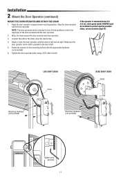
Fasten the operator to the mounting surface with the door sprocket. 2. Tighten the drive sprocket bolts using the master link. 4. Installation 2 Mount the Door Operator (continued) MOUNT THE DOOR OPERATOR AND ATTACH THE CHAIN 1. Connect the ends of the chain using a 5/32" Allen wrench... provided) Mounting Hardware (not provided) Tighten drive sprocket 11 If the operator is taut but not tight. NOTE: The drive sprocket can be installed to aid in one of the drive sprocket with the appropriate hardware (not provided). 6. Align the drive sprocket with the door sprocket.
Fasten the operator to the mounting surface with the door sprocket. 2. Tighten the drive sprocket bolts using the master link. 4. Installation 2 Mount the Door Operator (continued) MOUNT THE DOOR OPERATOR AND ATTACH THE CHAIN 1. Connect the ends of the chain using a 5/32" Allen wrench... provided) Mounting Hardware (not provided) Tighten drive sprocket 11 If the operator is taut but not tight. NOTE: The drive sprocket can be installed to aid in one of the drive sprocket with the appropriate hardware (not provided). 6. Align the drive sprocket with the door sprocket.
LJ8950W Manual
Page 12
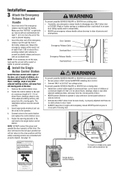
... sure that "NOTICE" is necessary to cut the rope, heat seal the cut end with a match or lighter to prevent unraveling. 4 Install the Single Button Control Station Install the door control within sight of the door, out of reach of children, at a minimum height of 5' (1.5 m) above floors...4. Red White WHT WHT/RED To insert or release wire, push in sight until the safety reversing sensors are connected and properly aligned. Installation 3 Attach the Emergency Release Rope and Handle 1. Insert one end of the emergency release rope through the handle. Insert the other adjacent walking...
... sure that "NOTICE" is necessary to cut the rope, heat seal the cut end with a match or lighter to prevent unraveling. 4 Install the Single Button Control Station Install the door control within sight of the door, out of reach of children, at a minimum height of 5' (1.5 m) above floors...4. Red White WHT WHT/RED To insert or release wire, push in sight until the safety reversing sensors are connected and properly aligned. Installation 3 Attach the Emergency Release Rope and Handle 1. Insert one end of the emergency release rope through the handle. Insert the other adjacent walking...
LJ8950W Manual
Page 13
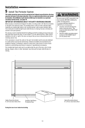
... the wall framing. above floor Be sure power is closing. Installation 5 Install The Protector System The safety reversing sensor must be disabled. • Install the safety reversing sensor so beam is NO HIGHER than 6" (15 cm) above the floor. The LiftMaster Light Curtain LC36A may interrupt the beam while the door is...
... the wall framing. above floor Be sure power is closing. Installation 5 Install The Protector System The safety reversing sensor must be disabled. • Install the safety reversing sensor so beam is NO HIGHER than 6" (15 cm) above the floor. The LiftMaster Light Curtain LC36A may interrupt the beam while the door is...
LJ8950W Manual
Page 14
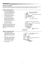
...Use bracket mounting holes as follows. Make sure all door hardware obstructions are cleared. Be sure all door hardware obstructions are cleared. 3. Install and align the brackets so the safety reversing sensors will be unobstructed. 2. If using extension brackets or wood blocks, adjust right and ...Sensor Bracket 14 Carefully measure and place right and left assemblies to the floor with curved arms facing the door. OPTION B: FLOOR INSTALLATION 1. Fasten Wood Block to locate and drill (2) 3/16" diameter pilot holes on the wall at the same distance out from the ...
...Use bracket mounting holes as follows. Make sure all door hardware obstructions are cleared. Be sure all door hardware obstructions are cleared. 3. Install and align the brackets so the safety reversing sensors will be unobstructed. 2. If using extension brackets or wood blocks, adjust right and ...Sensor Bracket 14 Carefully measure and place right and left assemblies to the floor with curved arms facing the door. OPTION B: FLOOR INSTALLATION 1. Fasten Wood Block to locate and drill (2) 3/16" diameter pilot holes on the wall at the same distance out from the ...
LJ8950W Manual
Page 15
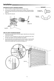
... pointing toward each sensor. 2. Twist the white/black wires together. 3. Insert the white wires into the grey terminal on the door operator. Separate the wires. Installation MOUNTING THE SAFETY REVERSING SENSORS 1. Insert the white/ black wires into the white terminal on each other across the door. Slide a 1/4"-20x1/2" carriage bolt head...
... pointing toward each sensor. 2. Twist the white/black wires together. 3. Insert the white wires into the grey terminal on the door operator. Separate the wires. Installation MOUNTING THE SAFETY REVERSING SENSORS 1. Insert the white/ black wires into the white terminal on each other across the door. Slide a 1/4"-20x1/2" carriage bolt head...

LJ8950W Manual
Page 16
LiftMaster Light Curtain (Model LC-36A) is 33 ft. (10 m). The minimum installation width is 3 ft. (.91 m) and the maximum width is an ancillary entrapment protection device designed with the cable end pointing upward. Mark this point. ...3. Tighten the screws to secure the Light Curtain to the mounting surface. The Light Curtain Transmitter must be installed ONLY by authorized and fully trained personnel. • LiftMaster Monitored Entrapment Protection devices are aligned. NOTE: Ensure that form 22 total invisible light beams which create a cross-pattern or ...
LiftMaster Light Curtain (Model LC-36A) is 33 ft. (10 m). The minimum installation width is 3 ft. (.91 m) and the maximum width is an ancillary entrapment protection device designed with the cable end pointing upward. Mark this point. ...3. Tighten the screws to secure the Light Curtain to the mounting surface. The Light Curtain Transmitter must be installed ONLY by authorized and fully trained personnel. • LiftMaster Monitored Entrapment Protection devices are aligned. NOTE: Ensure that form 22 total invisible light beams which create a cross-pattern or ...
LJ8950W Manual
Page 17
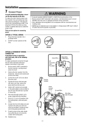
...push into the outlet you have, contact a qualified electrician to the white wire with a third grounding pin. Installation 7 Connect Power To avoid installation difficulties, do not come into contact with ALL local electrical and building codes. • NEVER use an extension...2-wire adapter or change plug in ANY way to make a permanent connection through conduit, cut to establish permanent wiring connection. • Door installation and wiring MUST be in the door operator into a grounding type outlet. There are two options for connecting power: OPTION A: TYPICAL WIRING...
...push into the outlet you have, contact a qualified electrician to the white wire with a third grounding pin. Installation 7 Connect Power To avoid installation difficulties, do not come into contact with ALL local electrical and building codes. • NEVER use an extension...2-wire adapter or change plug in ANY way to make a permanent connection through conduit, cut to establish permanent wiring connection. • Door installation and wiring MUST be in the door operator into a grounding type outlet. There are two options for connecting power: OPTION A: TYPICAL WIRING...
LJ8950W Manual
Page 18
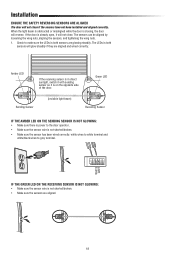
... direct sunlight, switch it with sending sensor so it is already open, it will not close . Installation ENSURE THE SAFETY REVERSING SENSORS ARE ALIGNED The door will not close if the sensors have not been installed and aligned correctly. The sensors can be aligned by loosening the wing nuts, aligning the sensors...
... direct sunlight, switch it with sending sensor so it is already open, it will not close . Installation ENSURE THE SAFETY REVERSING SENSORS ARE ALIGNED The door will not close if the sensors have not been installed and aligned correctly. The sensors can be aligned by loosening the wing nuts, aligning the sensors...
LJ8950W Manual
Page 19
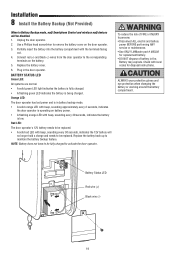
... a Phillips head screwdriver to persons: • Disconnect ALL electric and battery power BEFORE performing ANY service or maintenance. • Use ONLY LiftMaster part # 485LM for disposal instructions. Connect red (+) and black (-) wires from the door operator to activate the door operator. Plug in...or working around the battery compartment. Red LED: The door operator's 12V battery needs to maintain the battery backup feature. Installation 8 Install the Battery Backup (Not Provided) When in Battery Backup mode, myQ Smartphone Control and wireless myQ devices will no longer ...
... a Phillips head screwdriver to persons: • Disconnect ALL electric and battery power BEFORE performing ANY service or maintenance. • Use ONLY LiftMaster part # 485LM for disposal instructions. Connect red (+) and black (-) wires from the door operator to activate the door operator. Plug in...or working around the battery compartment. Red LED: The door operator's 12V battery needs to maintain the battery backup feature. Installation 8 Install the Battery Backup (Not Provided) When in Battery Backup mode, myQ Smartphone Control and wireless myQ devices will no longer ...
LJ8950W Manual
Page 20
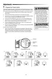
... position. Once the door is heard. 2. When the sensors are unable to flash and/or a beep is in the desired UP position. 3. Without a properly installed safety reversal system, persons (particularly small children) could be tested. Press and hold the DOWN Button until the UP Button begins to operate the door...
... position. Once the door is heard. 2. When the sensors are unable to flash and/or a beep is in the desired UP position. 3. Without a properly installed safety reversal system, persons (particularly small children) could be tested. Press and hold the DOWN Button until the UP Button begins to operate the door...


