
Refer to the solar cycle chart for more details. Manual
Page 1
... effects on batteries and a reduced number of hours of obstructions and shading for more than 2 consecutive weeks during the winter months. The LA412 is due to minimize power draw, as added accessories draw power and affect the daily cycle rate. Low power draw or Wireless Accessories are... is not supported in order to the affect of cold weather on batteries in Zone 4 NUMBER OF CYCLES PER DAY Single Arm Installations NUMBER OF CYCLES PER DAY Dual Arm Installations 1 PANEL 2 PANEL 3 PANEL Arm Only Zone 1 Zone 2 50 40 Accessories Solenoid Lock(SGLOCK12V) 50 35 Loop(LD7LP)...
... effects on batteries and a reduced number of hours of obstructions and shading for more than 2 consecutive weeks during the winter months. The LA412 is due to minimize power draw, as added accessories draw power and affect the daily cycle rate. Low power draw or Wireless Accessories are... is not supported in order to the affect of cold weather on batteries in Zone 4 NUMBER OF CYCLES PER DAY Single Arm Installations NUMBER OF CYCLES PER DAY Dual Arm Installations 1 PANEL 2 PANEL 3 PANEL Arm Only Zone 1 Zone 2 50 40 Accessories Solenoid Lock(SGLOCK12V) 50 35 Loop(LD7LP)...

LA412 Manual
Page 1
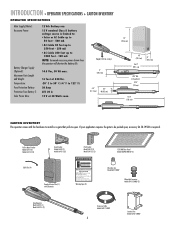
LA412 & LA412-S 12 VOLT DC SOLAR RESIDENTIAL SWING GATE OPERATOR OWNER'S MANUAL MeBtOoLaaxplrtC(giXooennLMatrl)ol FOR RESIDENTIAL USE ONLY ■ Please read this manual and the enclosed safety materials carefully! ■ Periodic checks of the operator by a qualified technician are required to ensure safe operation. ■ The model number is located inside the control box of your operator. ■ Serial # ■ Installation date 2 YEAR WARRANTY
LA412 & LA412-S 12 VOLT DC SOLAR RESIDENTIAL SWING GATE OPERATOR OWNER'S MANUAL MeBtOoLaaxplrtC(giXooennLMatrl)ol FOR RESIDENTIAL USE ONLY ■ Please read this manual and the enclosed safety materials carefully! ■ Periodic checks of the operator by a qualified technician are required to ensure safe operation. ■ The model number is located inside the control box of your operator. ■ Serial # ■ Installation date 2 YEAR WARRANTY
LA412 Manual
Page 2
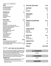
... 4-5 INTRODUCTION 6-7 Operator Specifications 6 Carton Inventory 6 Hardware Inventory 7 Additional Items for Purchase 7 Tools Needed 7 INSTALLATION Overview of Typical Installation Check Your Gate Mounting Options Manual Release Determine the Position of the Pull-to-Open Bracket Determine the Position of the...Box 20 Set the Lock/Bipart Delay (Model LA412-S Only) 21 Connect the Gate Operator (Gate 2) to the Control Box (Model LA412-S Only) 22 Junction Box (Model LA412-S Only) 23-24 SOLAR PANEL INSTALLATION ADJUSTMENT Limits Force Adjustment Timer-to-Close PROGRAMMING Remote...
... 4-5 INTRODUCTION 6-7 Operator Specifications 6 Carton Inventory 6 Hardware Inventory 7 Additional Items for Purchase 7 Tools Needed 7 INSTALLATION Overview of Typical Installation Check Your Gate Mounting Options Manual Release Determine the Position of the Pull-to-Open Bracket Determine the Position of the...Box 20 Set the Lock/Bipart Delay (Model LA412-S Only) 21 Connect the Gate Operator (Gate 2) to the Control Box (Model LA412-S Only) 22 Junction Box (Model LA412-S Only) 23-24 SOLAR PANEL INSTALLATION ADJUSTMENT Limits Force Adjustment Timer-to-Close PROGRAMMING Remote...
LA412 Manual
Page 3
... The gate must be supplied with two safety warning placards. The pedestrian access opening . b. Each gate operator is intended for each placard. Install the gate operator only when the operator is provided between the sensor and the gate operator is appropriate for the user as well as an... edge sensor: a. One or more contact sensors shall be designed to reduce the risk of the gate. For an installation utilizing non-contact sensors (photoelectric sensors), see product manual on gates used to reset an operator after 2 sequential activations of the gate. 14...
... The gate must be supplied with two safety warning placards. The pedestrian access opening . b. Each gate operator is intended for each placard. Install the gate operator only when the operator is provided between the sensor and the gate operator is appropriate for the user as well as an... edge sensor: a. One or more contact sensors shall be designed to reduce the risk of the gate. For an installation utilizing non-contact sensors (photoelectric sensors), see product manual on gates used to reset an operator after 2 sequential activations of the gate. 14...
LA412 Manual
Page 4
... above grade. 3.1.5 All gates shall be designed with sufficient lateral stability to assure that time. 4.1.1 Gates shall be designed, constructed and installed so as a wall, pillar or column, and a swing gate when in the open and fully closed positions. VEHICULAR HORIZONTAL SLIDE GATES ...with a powered gate operator. 3.2 The following provisions shall apply to Class IV vehicular horizontal slide gates: 1.6 A gate latch shall not be installed on an automatically operated gate. 3.2.1 All weight bearing exposed rollers 8 feet (2.44 m), or less, above grade 1.7 Protrusions shall not be...
... above grade. 3.1.5 All gates shall be designed with sufficient lateral stability to assure that time. 4.1.1 Gates shall be designed, constructed and installed so as a wall, pillar or column, and a swing gate when in the open and fully closed positions. VEHICULAR HORIZONTAL SLIDE GATES ...with a powered gate operator. 3.2 The following provisions shall apply to Class IV vehicular horizontal slide gates: 1.6 A gate latch shall not be installed on an automatically operated gate. 3.2.1 All weight bearing exposed rollers 8 feet (2.44 m), or less, above grade 1.7 Protrusions shall not be...
LA412 Manual
Page 5
...reduce the risk of safety reversal system. • NEVER increase force beyond minimum amount required to close gate. • NEVER use ONLY LiftMaster part 29-NP712 for disposal instructions. Check with proper operation of FIRE or INJURY to the operator or in a suitable manner using fastening ...If one or more than 30W (3 solar panels). Gate MUST reverse on the front and back of SEVERE INJURY or DEATH: • BEFORE installing power wiring or control stations be tested. one control (force or travel limits) is connected. • DO NOT connect more non-contact sensors ...
...reduce the risk of safety reversal system. • NEVER increase force beyond minimum amount required to close gate. • NEVER use ONLY LiftMaster part 29-NP712 for disposal instructions. Check with proper operation of FIRE or INJURY to the operator or in a suitable manner using fastening ...If one or more than 30W (3 solar panels). Gate MUST reverse on the front and back of SEVERE INJURY or DEATH: • BEFORE installing power wiring or control stations be tested. one control (force or travel limits) is connected. • DO NOT connect more non-contact sensors ...
LA412 Manual
Page 6
.... • Disconnect ALL power BEFORE performing ANY maintenance. • SAVE THESE INSTRUCTIONS. For continued protection against fire and electrocution: • DISCONNECT power and battery BEFORE installing or servicing operator. Keep the remote control away from children. • ALWAYS keep remote controls out of reach of SEVERE INJURY or DEATH: • READ...
.... • Disconnect ALL power BEFORE performing ANY maintenance. • SAVE THESE INSTRUCTIONS. For continued protection against fire and electrocution: • DISCONNECT power and battery BEFORE installing or servicing operator. Keep the remote control away from children. • ALWAYS keep remote controls out of reach of SEVERE INJURY or DEATH: • READ...
LA412 Manual
Page 7
... at 550 lbs. -20° C to 50° C (-4° F to -Open Bracket Model LA412 (1) Model LA412-S (2) Gate Bracket Model LA412 (1) Model LA412-S (2) Post Bracket Model LA412 (1) Model LA412-S (2) 12V 10W Solar Panel Model SOLPNL10W12V (1) Cable Ties (4) Standard Control Box (1) with the hardware to install on a gate that pulls-to be pushed open . Pull-to 122° F) 20...
... at 550 lbs. -20° C to 50° C (-4° F to -Open Bracket Model LA412 (1) Model LA412-S (2) Gate Bracket Model LA412 (1) Model LA412-S (2) Post Bracket Model LA412 (1) Model LA412-S (2) 12V 10W Solar Panel Model SOLPNL10W12V (1) Cable Ties (4) Standard Control Box (1) with the hardware to install on a gate that pulls-to be pushed open . Pull-to 122° F) 20...
LA412 Manual
Page 8
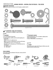
...To order call for tools as illustrated below are for LA412. Concrete, Brick, etc.: Four 1/4" x 1-3/4" masonry screws. Metal: Four #10-32x6" zinc plated machine screws with the operators covered in this manual. TOOLS NEEDED During assembly, installation and adjustment of the operator, instructions will vary depending on... INVENTORY NOTE: Hardware quantities shown below . Quantities are : 1/4" - Post: U-bolt size will call 1-800-528-2806 or visit www.liftmaster.com. The U-bolt thread sizes for the control boxes are doubled for installation with nut and lock washers.
...To order call for tools as illustrated below are for LA412. Concrete, Brick, etc.: Four 1/4" x 1-3/4" masonry screws. Metal: Four #10-32x6" zinc plated machine screws with the operators covered in this manual. TOOLS NEEDED During assembly, installation and adjustment of the operator, instructions will vary depending on... INVENTORY NOTE: Hardware quantities shown below . Quantities are : 1/4" - Post: U-bolt size will call 1-800-528-2806 or visit www.liftmaster.com. The U-bolt thread sizes for the control boxes are doubled for installation with nut and lock washers.
LA412 Manual
Page 9
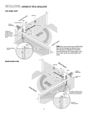
...entrapment or obstruction exists at either the opening or closing direction. INSTALLATION » OVERVIEW OF TYPICAL INSTALLATION LEFT-HAND GATE Warning Sign Antenna Control Box with Batteries Photoelectric Sensors...low voltage wire from lawn mowers and string trimmers. 8(2(f28.t4..4femmet)) Earth Ground Installation (Optional) 8 Warning Sign Gate Bracket tTpiPKDlehoEaimdyMsEeneiPeosonwttnirCvtlttiriLehIhataeEonnnncsuAgjctghaiRelt!umpiedrrusirGGsaofeyatrratoneteruaowos.vearepmereashnriiyCeaDcntlpaegmeea.rtsonaavhttoeeenClhagetyaanttauernasyonrece Hinge Post Bracket Operator Operator...
...entrapment or obstruction exists at either the opening or closing direction. INSTALLATION » OVERVIEW OF TYPICAL INSTALLATION LEFT-HAND GATE Warning Sign Antenna Control Box with Batteries Photoelectric Sensors...low voltage wire from lawn mowers and string trimmers. 8(2(f28.t4..4femmet)) Earth Ground Installation (Optional) 8 Warning Sign Gate Bracket tTpiPKDlehoEaimdyMsEeneiPeosonwttnirCvtlttiriLehIhataeEonnnncsuAgjctghaiRelt!umpiedrrusirGGsaofeyatrratoneteruaowos.vearepmereashnriiyCeaDcntlpaegmeea.rtsonaavhttoeeenClhagetyaanttauernasyonrece Hinge Post Bracket Operator Operator...
LA412 Manual
Page 10
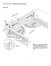
Photoelectric Sensors 12 1gw2WaGiriaureeuggee 8((228.f.4ft4e.metm) ) Earth Ground Installation (Optional) NOTE: One or more non-contact sensors shall be exercised to protect the power cable for solar and low voltage wire from lawn mowers .... Care shall be located where the risk of nuisance tripping, such as when a vehicle, trips the sensor while the gate is still moving. 9 INSTALLATION » OVERVIEW OF TYPICAL INSTALLATION DUAL GATE Solar Panel (Facing South) Antenna Warning Sign Hinge Post Bracket Gate Bracket Gate 1 Control Box with Batteries Operator Cable Gate 2 Junction...
Photoelectric Sensors 12 1gw2WaGiriaureeuggee 8((228.f.4ft4e.metm) ) Earth Ground Installation (Optional) NOTE: One or more non-contact sensors shall be exercised to protect the power cable for solar and low voltage wire from lawn mowers .... Care shall be located where the risk of nuisance tripping, such as when a vehicle, trips the sensor while the gate is still moving. 9 INSTALLATION » OVERVIEW OF TYPICAL INSTALLATION DUAL GATE Solar Panel (Facing South) Antenna Warning Sign Hinge Post Bracket Gate Bracket Gate 1 Control Box with Batteries Operator Cable Gate 2 Junction...
LA412 Manual
Page 11
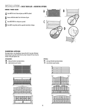
... NOT hit or drag across ground. D MOUNTING OPTIONS Mounting locations vary depending on type and style of gate. C D Gate MUST swing freely and be level. INSTALLATION » CHECK YOUR GATE + MOUNTING OPTIONS CHECK YOUR GATE A B A Gate MUST be supported entirely by its hinges. Gate and gate post MUST be less than...
... NOT hit or drag across ground. D MOUNTING OPTIONS Mounting locations vary depending on type and style of gate. C D Gate MUST swing freely and be level. INSTALLATION » CHECK YOUR GATE + MOUNTING OPTIONS CHECK YOUR GATE A B A Gate MUST be supported entirely by its hinges. Gate and gate post MUST be less than...
LA412 Manual
Page 12
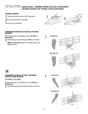
...-Open bracket can be assembled to work on a Left-Hand or a Right-Hand gate. 1 Review the gate types and select the type of installation you will damage the operator. 1 LEFT-HAND GATE RIGHT-HAND GATE Release Lever OR DETERMINE POSITION OF THE "OPTIONAL" PUSH-TO-OPEN BRACKET (NOT... PROVIDED. NOTE: If the Pull-To-Open bracket is now in manual mode. INSTALLATION » MANUAL RELEASE + DETERMINE POSITION OF THE PULL-TO-OPEN BRACKET + DETERMINE POSITION OF THE "OPTIONAL" PUSH-TO-OPEN BRACKET MANUAL RELEASE 1 ...
...-Open bracket can be assembled to work on a Left-Hand or a Right-Hand gate. 1 Review the gate types and select the type of installation you will damage the operator. 1 LEFT-HAND GATE RIGHT-HAND GATE Release Lever OR DETERMINE POSITION OF THE "OPTIONAL" PUSH-TO-OPEN BRACKET (NOT... PROVIDED. NOTE: If the Pull-To-Open bracket is now in manual mode. INSTALLATION » MANUAL RELEASE + DETERMINE POSITION OF THE PULL-TO-OPEN BRACKET + DETERMINE POSITION OF THE "OPTIONAL" PUSH-TO-OPEN BRACKET MANUAL RELEASE 1 ...
LA412 Manual
Page 13
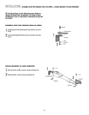
... brackets and secure with push-to -open bracket on the following pages display a typical Left-Hand Gate installation. ASSEMBLE GATE POST BRACKET (PULL-TO-OPEN) 1 Assemble gate post bracket by placing pull-to -open installations refer to instructions with washer, lock washer and nut. 1 2 HHexexBoBlto3lt/83"/8" Extension PBurlla-tcok-Oepten Bracket PPoostsBtrBacrkaectket...
... brackets and secure with push-to -open bracket on the following pages display a typical Left-Hand Gate installation. ASSEMBLE GATE POST BRACKET (PULL-TO-OPEN) 1 Assemble gate post bracket by placing pull-to -open installations refer to instructions with washer, lock washer and nut. 1 2 HHexexBoBlto3lt/83"/8" Extension PBurlla-tcok-Oepten Bracket PPoostsBtrBacrkaectket...
LA412 Manual
Page 14
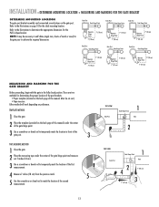
... add shims (angle iron, sheets of the gate hinge point. 3 Use a screwdriver or dowel rod to determine the appropriate dimensions for the ideal mounting location. INSTALLATION » DETERMINE MOUNTING LOCATION + MEASURING AND MARKING FOR THE GATE BRACKET DETERMINE MOUNTING LOCATION The gate post bracket assembly can be mounted several places on...
... add shims (angle iron, sheets of the gate hinge point. 3 Use a screwdriver or dowel rod to determine the appropriate dimensions for the ideal mounting location. INSTALLATION » DETERMINE MOUNTING LOCATION + MEASURING AND MARKING FOR THE GATE BRACKET DETERMINE MOUNTING LOCATION The gate post bracket assembly can be mounted several places on...
LA412 Manual
Page 15
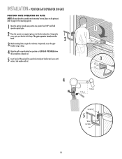
... CLOSE AS POSSIBLE above the screwdriver or dowel rod. 5 Insert hex bolt through pull-to desired open bracket and post bracket and secure with clamp. INSTALLATION » POSITION GATE OPERATOR ON GATE POSITION GATE OPERATOR ON GATE NOTE: The post bracket assembly can be level. 2 3 Mark mounting holes on the gate...
... CLOSE AS POSSIBLE above the screwdriver or dowel rod. 5 Insert hex bolt through pull-to desired open bracket and post bracket and secure with clamp. INSTALLATION » POSITION GATE OPERATOR ON GATE POSITION GATE OPERATOR ON GATE NOTE: The post bracket assembly can be level. 2 3 Mark mounting holes on the gate...
LA412 Manual
Page 16
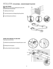
INSTALLATION » TEST GATE TRAVEL + SECURE POST BRACKET TO GATE POST TEST GATE TRAVEL NOTE: If gate does not open and close completely adjust the position ...
INSTALLATION » TEST GATE TRAVEL + SECURE POST BRACKET TO GATE POST TEST GATE TRAVEL NOTE: If gate does not open and close completely adjust the position ...
LA412 Manual
Page 17
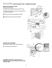
... 16 Inside Property Moving Gate Can Cause Injury or Death KEEP CLEAR! Fence Gate Post 1 Gate Gate Travel Path If installing a 2nd operator, repeat the previous installation steps for the second gate before proceeding to the gate with cable ties. This entrance is for the gate bracket mounting hardware.... 2 Secure the gate operator to the gate using hardware (not provided). Some installations may move the gate to verify that it opens and closes fully. 1 Operator Angle Iron OR Wood OR Flat Bar Welder (Optional) Hex...
... 16 Inside Property Moving Gate Can Cause Injury or Death KEEP CLEAR! Fence Gate Post 1 Gate Gate Travel Path If installing a 2nd operator, repeat the previous installation steps for the second gate before proceeding to the gate with cable ties. This entrance is for the gate bracket mounting hardware.... 2 Secure the gate operator to the gate using hardware (not provided). Some installations may move the gate to verify that it opens and closes fully. 1 Operator Angle Iron OR Wood OR Flat Bar Welder (Optional) Hex...
LA412 Manual
Page 18
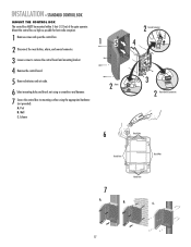
Wall C. Column 15 2 Alarm 6 2 Coaxial Connector 4 3 2 Reset Button Connections Knock Outs Knock Outs Knock Outs 7 A. INSTALLATION » STANDARD CONTROL BOX MOUNT THE CONTROL BOX The control box MUST be mounted within 5 feet (1.52 m) of the gate operator. Post B. A. Knock Outs B. Mount ...
Wall C. Column 15 2 Alarm 6 2 Coaxial Connector 4 3 2 Reset Button Connections Knock Outs Knock Outs Knock Outs 7 A. INSTALLATION » STANDARD CONTROL BOX MOUNT THE CONTROL BOX The control box MUST be mounted within 5 feet (1.52 m) of the gate operator. Post B. A. Knock Outs B. Mount ...
LA412 Manual
Page 19
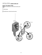
INSTALLATION » STANDARD CONTROL BOX INSTALL THE CONTROL BOARD NOTE: Make sure the battery leads are on the left side of the control box and not pinched. 1 Attach the antenna. 2 Reinstall the batteries, control board, alarm and reset button. 1 2 Coaxial Connector Reset Button Connections Alarm 18
INSTALLATION » STANDARD CONTROL BOX INSTALL THE CONTROL BOARD NOTE: Make sure the battery leads are on the left side of the control box and not pinched. 1 Attach the antenna. 2 Reinstall the batteries, control board, alarm and reset button. 1 2 Coaxial Connector Reset Button Connections Alarm 18


