GT- Logic 4 Installation Manual
Page 1
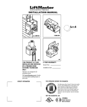
... TO BE INSTALLED AND SERVICED BY A TRAINED DOOR SYSTEMS TECHNICIAN ONLY. CONTACT INFORMATION GT 2 YEAR WARRANTY Serial # Box Installation Date THIS OPERATOR FEATURES THE ENHANCED M A E M E C AL INTENAN E PATENT PENDING R T T SYS The Maintenance Alert System™ allows the installer to locate ...a professional installing dealer in C2 operating mode. NOT FOR RESIDENTIAL USE 315MHz Radio Receiver Built on the 3-button station will signal when the set an internal Maintenance Cycle Counter. Visit www.liftmaster.com to set number of cycles/months is reached...
... TO BE INSTALLED AND SERVICED BY A TRAINED DOOR SYSTEMS TECHNICIAN ONLY. CONTACT INFORMATION GT 2 YEAR WARRANTY Serial # Box Installation Date THIS OPERATOR FEATURES THE ENHANCED M A E M E C AL INTENAN E PATENT PENDING R T T SYS The Maintenance Alert System™ allows the installer to locate ...a professional installing dealer in C2 operating mode. NOT FOR RESIDENTIAL USE 315MHz Radio Receiver Built on the 3-button station will signal when the set an internal Maintenance Cycle Counter. Visit www.liftmaster.com to set number of cycles/months is reached...

GT- Logic 4 Installation Manual
Page 2
... (LMEP 20 Install the Photoelectric Sensors (Provided 21 Mount the Photoelectric Sensors (Provided 22 Wire the LiftMaster Monitored Entrapment Protection (LMEP) Devices 22 ADJUSTMENT 23-24 Limit Adjustment 23 Clutch Adjustment (Belt Drive Model Operators 24 TESTING 25 MANUAL RELEASE 26-27 Emergency Disconnect System Model GT and T 26 Emergency Disconnect System...
... (LMEP 20 Install the Photoelectric Sensors (Provided 21 Mount the Photoelectric Sensors (Provided 22 Wire the LiftMaster Monitored Entrapment Protection (LMEP) Devices 22 ADJUSTMENT 23-24 Limit Adjustment 23 Clutch Adjustment (Belt Drive Model Operators 24 TESTING 25 MANUAL RELEASE 26-27 Emergency Disconnect System Model GT and T 26 Emergency Disconnect System...

GT- Logic 4 Installation Manual
Page 3
... Words on the following pages, it . Disable ALL locks and remove ALL ropes connected to door BEFORE installing operator to the possibility of the door. 9. SAVE THESE INSTARADUDVCVTEEIRORNTTSEE.NNCCIIAA PRAEDCVAERUTCEIÓNNCIA ADVERTENCIA 3 Safety Information Install ...1. SAFETY INFORMATION SAFETY INFORMATION WARNING Mechanical CWAWAUARTRINONINNINGG Electrical CWAUATRIONINNG WARNING IMPORTANT NOTES: • BEFORE attempting to install, operate or maintain the operator, you must read and fully understand this Signal Word on the following pages, they will alert you to the ...
... Words on the following pages, it . Disable ALL locks and remove ALL ropes connected to door BEFORE installing operator to the possibility of the door. 9. SAVE THESE INSTARADUDVCVTEEIRORNTTSEE.NNCCIIAA PRAEDCVAERUTCEIÓNNCIA ADVERTENCIA 3 Safety Information Install ...1. SAFETY INFORMATION SAFETY INFORMATION WARNING Mechanical CWAWAUARTRINONINNINGG Electrical CWAUATRIONINNG WARNING IMPORTANT NOTES: • BEFORE attempting to install, operate or maintain the operator, you must read and fully understand this Signal Word on the following pages, they will alert you to the ...

GT- Logic 4 Installation Manual
Page 4
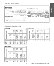
... feet. LIMIT ADJUST Linear driven, fully adjustable screw type cams. Adjustable to the bottom edge of door. ENTRAPMENT PROTECTION: LiftMaster Monitored Entrapment Protection (LMEP) Photoelectric Sensors (CPS-U Through beam used to open override. OPERATOR SPECIFICATIONS MOTOR TYPE Continuous duty HORSEPOWER: Model APT 1/2 HP Model GT 1/2, 3/4, 1 and 1-1/2 HP Model T 1/3, 1/2, 3/4 and 1 HP SPEED (At...
... feet. LIMIT ADJUST Linear driven, fully adjustable screw type cams. Adjustable to the bottom edge of door. ENTRAPMENT PROTECTION: LiftMaster Monitored Entrapment Protection (LMEP) Photoelectric Sensors (CPS-U Through beam used to open override. OPERATOR SPECIFICATIONS MOTOR TYPE Continuous duty HORSEPOWER: Model APT 1/2 HP Model GT 1/2, 3/4, 1 and 1-1/2 HP Model T 1/3, 1/2, 3/4 and 1 HP SPEED (At...
GT- Logic 4 Installation Manual
Page 5
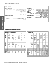
...16 ga. Steel Insul. 100 STANDARD SECTIONAL MODEL GT --- Steel Alum. Steel Wood Doors 24 ga. Steel Insul. 200 250 300 380 5 Operator specifications/Maximum door area - FT.) STANDARD SECTIONAL MODEL T --- Fiberglass Doors 24 ga. 22 ga. Steel Insul. 125 200 275 ...Steel Insul. 150 --- --- 16 ga. Doors --- --- 1/2 HP 400 350 3/4 HP 560 500 1 HP 625 575 1-1/2 HP --- 625 20 ga. TROLLEY OPERATOR SPECIFICATIONS MECHANICAL DRIVE REDUCTION: Model APT and T Primary: Heavy duty (5L) V-Belt Secondary: #41 chain/sprocket; Steel Insul. 260 320 450 560 16 ga. Doors...
...16 ga. Steel Insul. 100 STANDARD SECTIONAL MODEL GT --- Steel Alum. Steel Wood Doors 24 ga. Steel Insul. 200 250 300 380 5 Operator specifications/Maximum door area - FT.) STANDARD SECTIONAL MODEL T --- Fiberglass Doors 24 ga. 22 ga. Steel Insul. 125 200 275 ...Steel Insul. 150 --- --- 16 ga. Doors --- --- 1/2 HP 400 350 3/4 HP 560 500 1 HP 625 575 1-1/2 HP --- 625 20 ga. TROLLEY OPERATOR SPECIFICATIONS MECHANICAL DRIVE REDUCTION: Model APT and T Primary: Heavy duty (5L) V-Belt Secondary: #41 chain/sprocket; Steel Insul. 260 320 450 560 16 ga. Doors...
GT- Logic 4 Installation Manual
Page 7
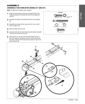
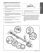
... flange hex nuts (B). 2 Install the front idler to page 9. 1 Install the track spacers evenly over the length of the track and the operator. Trolley TROLLEY ASSEMBLY ASSEMBLE THE OPERATOR (MODELS T AND GT) NOTE: For Model APT assembly refer to the track with bolts (F) and washers (D). 3 Assemble the trolley with the take.... 6 Slide bolts (A) on the end of the track assembly into the holes on the end of the track. Insert bolts (A) into the "L" slot in the operator and tighten nuts (B).
... flange hex nuts (B). 2 Install the front idler to page 9. 1 Install the track spacers evenly over the length of the track and the operator. Trolley TROLLEY ASSEMBLY ASSEMBLE THE OPERATOR (MODELS T AND GT) NOTE: For Model APT assembly refer to the track with bolts (F) and washers (D). 3 Assemble the trolley with the take.... 6 Slide bolts (A) on the end of the track assembly into the holes on the end of the track. Insert bolts (A) into the "L" slot in the operator and tighten nuts (B).
GT- Logic 4 Installation Manual
Page 8
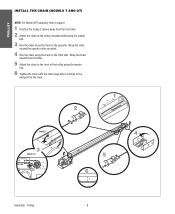
.... 5 Attach the chain to the front of the track. 2 1 2˝ MODEL T 3 MODEL GT 4 5 6 3˝ Assembly - Wrap the chain around the operator drive sprocket. 4 Run the chain along the track to the operator. TROLLEY INSTALL THE CHAIN (MODELS T AND GT) NOTE: For Model APT assembly refer to page 9. 1 Position the trolley 2 inches away...
.... 5 Attach the chain to the front of the track. 2 1 2˝ MODEL T 3 MODEL GT 4 5 6 3˝ Assembly - Wrap the chain around the operator drive sprocket. 4 Run the chain along the track to the operator. TROLLEY INSTALL THE CHAIN (MODELS T AND GT) NOTE: For Model APT assembly refer to page 9. 1 Position the trolley 2 inches away...
GT- Logic 4 Installation Manual
Page 9
... trolley back and forth past the drive chain to ensure there is not an APT, proceed to be loosened or tightened to the operator. Wrap the chain around the operator drive sprocket. 2 6 1 3 8 9 10 3˝ 9 4 7 5 Assembly - The take-up bolt can be cut for proper adjustment. Wrap the chain around the front ... the end of the track assembly into the "L" slot in the second set of holes on the end of the bolts. Trolley TROLLEY ASSEMBLE THE OPERATOR (MODEL APT) NOTE: If your model is no binding. 7 Run the chain along the track to the free end of the drive link using a master...
... trolley back and forth past the drive chain to ensure there is not an APT, proceed to be loosened or tightened to the operator. Wrap the chain around the operator drive sprocket. 2 6 1 3 8 9 10 3˝ 9 4 7 5 Assembly - The take-up bolt can be cut for proper adjustment. Wrap the chain around the front ... the end of the track assembly into the "L" slot in the second set of holes on the end of the bolts. Trolley TROLLEY ASSEMBLE THE OPERATOR (MODEL APT) NOTE: If your model is no binding. 7 Run the chain along the track to the free end of the drive link using a master...
GT- Logic 4 Installation Manual
Page 10
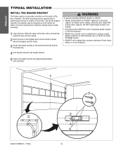
TROLLEY TYPICAL INSTALLATION INSTALL THE HEADER BRACKET The trolley operator is out of the door. Extension springs require center mounting. 1 Close the door. WARNING To prevent possible SERIOUS INJURY or DEATH: CAUTION • Header bracket ... center mounting may be required due to 24 inches off center on header wall or ceiling, otherwise door might NOT reverse when required. Typically, the operator may be mounted up to interfering structures or location of travel mark 4 inches above the highest point of door stile / top section support. Mark the...
TROLLEY TYPICAL INSTALLATION INSTALL THE HEADER BRACKET The trolley operator is out of the door. Extension springs require center mounting. 1 Close the door. WARNING To prevent possible SERIOUS INJURY or DEATH: CAUTION • Header bracket ... center mounting may be required due to 24 inches off center on header wall or ceiling, otherwise door might NOT reverse when required. Typically, the operator may be mounted up to interfering structures or location of travel mark 4 inches above the highest point of door stile / top section support. Mark the...
GT- Logic 4 Installation Manual
Page 11
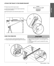
.... TROLLEY ATTACH THE TRACK TO THE HEADER BRACKET 1 Align the track with the fasteners. 3 Swing the operator up and ensure the operator is level. HARDWARE Header Pivot Pin (1) Cotter pins (2) 1 2 3 WARNING HANG THE OPERATOR 1 Secure the operator using the appropriate fasteners and locking hardware that will support the weight of the building. • Concrete...
.... TROLLEY ATTACH THE TRACK TO THE HEADER BRACKET 1 Align the track with the fasteners. 3 Swing the operator up and ensure the operator is level. HARDWARE Header Pivot Pin (1) Cotter pins (2) 1 2 3 WARNING HANG THE OPERATOR 1 Secure the operator using the appropriate fasteners and locking hardware that will support the weight of the building. • Concrete...
GT- Logic 4 Installation Manual
Page 12
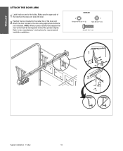
... Nut 3/8"-16 (2) B Nylok Nut 3/8"-16 (1) Bolt 3/8"-16 x 1" (3) NOTICE 1 A B 2 Typical installation - NOTE: When properly installed and adjusted the door arm should be leaning back toward the operator slightly. Trolley 12 Refer to door manufacturer's instructions for recommended installation guidelines.
... Nut 3/8"-16 (2) B Nylok Nut 3/8"-16 (1) Bolt 3/8"-16 x 1" (3) NOTICE 1 A B 2 Typical installation - NOTE: When properly installed and adjusted the door arm should be leaning back toward the operator slightly. Trolley 12 Refer to door manufacturer's instructions for recommended installation guidelines.

GT- Logic 4 Installation Manual
Page 13
... WIRING TYPE C2 (Standard) Momentary contact to OPEN and STOP, constant pressure to CLOSE, plus wiring for manual door operation Model HJ Includes both floor level disconnect systems stated above ENTRAPMENT PROTECTION: LiftMaster Monitored Entrapment Protection (LMEP) Photoelectric Sensors (CPS-U Through beam used to open and close with open override. LIMIT ADJUST...
... WIRING TYPE C2 (Standard) Momentary contact to OPEN and STOP, constant pressure to CLOSE, plus wiring for manual door operation Model HJ Includes both floor level disconnect systems stated above ENTRAPMENT PROTECTION: LiftMaster Monitored Entrapment Protection (LMEP) Photoelectric Sensors (CPS-U Through beam used to open and close with open override. LIMIT ADJUST...
GT- Logic 4 Installation Manual
Page 14
... WHEEL Left or right handing Models H and HJ ONLY HOIST WHEEL Standard mounting on left or right side HOIST AND JACKSHAFT MAXIMUM DOOR AREA (SQ. OPERATOR SPECIFICATIONS MECHANICAL DRIVE REDUCTION: Model J, H, and HJ Primary: Heavy duty (5L) V-Belt Secondary: #48 chain/sprocket; Output: #50 chain Model GH ... 400 16 ga. Steel Wood Doors 24 ga. Steel Steel ROLLING Alum. Doors 24 ga. 22 ga. Steel Insul. 175 225 300 375 460 620 Operator specifications/Maximum door area - Doors SECTIONAL --- --- 1/3 HP 310 285 1/2 HP 400 350 3/4 HP 560 500 1 HP 640 625 --- ---...
... WHEEL Left or right handing Models H and HJ ONLY HOIST WHEEL Standard mounting on left or right side HOIST AND JACKSHAFT MAXIMUM DOOR AREA (SQ. OPERATOR SPECIFICATIONS MECHANICAL DRIVE REDUCTION: Model J, H, and HJ Primary: Heavy duty (5L) V-Belt Secondary: #48 chain/sprocket; Output: #50 chain Model GH ... 400 16 ga. Steel Wood Doors 24 ga. Steel Steel ROLLING Alum. Doors 24 ga. 22 ga. Steel Insul. 175 225 300 375 460 620 Operator specifications/Maximum door area - Doors SECTIONAL --- --- 1/3 HP 310 285 1/2 HP 400 350 3/4 HP 560 500 1 HP 640 625 --- ---...
GT- Logic 4 Installation Manual
Page 15
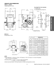
...59.51 cm) Hand Chain Wheel Present with 1" x 1/4" key for 1/2 thru 1 HP operators, 1-3/16" x 5/16" key for 1-1/2 and 2 HP operators, 1-1/4" x 1/4" key for 3 HP operators. 2) Mounting centers: X = 4-3/4"; Y = 9-1/16" for 1/2 thru 2 HP operators. X = 3-5/8"; WEIGHTS AND DIMENSIONS HANGING WEIGHT: .........80-110 LBS. 14" (35.1546 "...cm) HOIST AND JACKSHAFT MODEL GH Hanging Weight: 140 lbs. Y = 5-1/2" for 3 HP operators. 3) Hand chain wheel extends 1-5/8" beyond operator in vertical mounting position as shown. 15 Weights and dimensions - Hoist and Jackshaft WEIGHTS AND DIMENSIONS...
...59.51 cm) Hand Chain Wheel Present with 1" x 1/4" key for 1/2 thru 1 HP operators, 1-3/16" x 5/16" key for 1-1/2 and 2 HP operators, 1-1/4" x 1/4" key for 3 HP operators. 2) Mounting centers: X = 4-3/4"; Y = 9-1/16" for 1/2 thru 2 HP operators. X = 3-5/8"; WEIGHTS AND DIMENSIONS HANGING WEIGHT: .........80-110 LBS. 14" (35.1546 "...cm) HOIST AND JACKSHAFT MODEL GH Hanging Weight: 140 lbs. Y = 5-1/2" for 3 HP operators. 3) Hand chain wheel extends 1-5/8" beyond operator in vertical mounting position as shown. 15 Weights and dimensions - Hoist and Jackshaft WEIGHTS AND DIMENSIONS...

GT- Logic 4 Installation Manual
Page 16
...SERIOUS PERSONAL INJURY. • Disable ALL locks and remove ALL ropes connected to door AVERTISSEMENT BEFORE installing and operating door operator to avoid entanglement. • Fasten the operator SECURELY to remain functional, install an interlock switch. • ALWAYS call a trained door systems technician if ... 1b ADVERTENCIA ADVERTENCIA 12" - 15" Assembly/Typical installation - An unbalanced door may be switched. The optimum distance between the operator and the door shaft. AVERTISSEMENT For models H and HJ with the drive shaft parallel to be determined at the time of ...
...SERIOUS PERSONAL INJURY. • Disable ALL locks and remove ALL ropes connected to door AVERTISSEMENT BEFORE installing and operating door operator to avoid entanglement. • Fasten the operator SECURELY to remain functional, install an interlock switch. • ALWAYS call a trained door systems technician if ... 1b ADVERTENCIA ADVERTENCIA 12" - 15" Assembly/Typical installation - An unbalanced door may be switched. The optimum distance between the operator and the door shaft. AVERTISSEMENT For models H and HJ with the drive shaft parallel to be determined at the time of ...

GT- Logic 4 Installation Manual
Page 17
... the master link. 4 Align the door and the drive sprockets. MOUNTING 1 Place the door sprocket on the door shaft. 2 Place the operator drive sprocket on the appropriate side of the operator for your installation type. 3 Wrap the drive chain around the door sprocket and the drive sprocket then secure with the set...
... the master link. 4 Align the door and the drive sprockets. MOUNTING 1 Place the door sprocket on the door shaft. 2 Place the operator drive sprocket on the appropriate side of the operator for your installation type. 3 Wrap the drive chain around the door sprocket and the drive sprocket then secure with the set...
GT- Logic 4 Installation Manual
Page 18
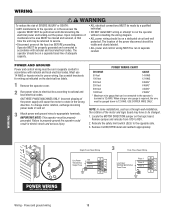
...phasing of the motor and logic board may be returned to service. • Disconnect power at the fuse box BEFORE proceeding. IMPORTANT NOTE: This operator must be properly grounded. Failure to REV. 2. The location of adequate capacity. • ALL electrical connections MUST be made by a qualified ...local electrical codes. USE COPPER WIRE ONLY. NOTE: In some installations, such as indicated on the electrical box labels. 1 Remove the operator cover. 2 Run power wires to electrical box according to national and local electrical codes. Power and ground wiring 18 Remove jumper and...
...phasing of the motor and logic board may be returned to service. • Disconnect power at the fuse box BEFORE proceeding. IMPORTANT NOTE: This operator must be properly grounded. Failure to REV. 2. The location of adequate capacity. • ALL electrical connections MUST be made by a qualified ...local electrical codes. USE COPPER WIRE ONLY. NOTE: In some installations, such as indicated on the electrical box labels. 1 Remove the operator cover. 2 Run power wires to electrical box according to national and local electrical codes. Power and ground wiring 18 Remove jumper and...
GT- Logic 4 Installation Manual
Page 19
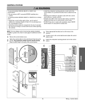
... prevent the user from coming in sight until completely closed. Door May Move at any Time Without Prior Warning Do Not Let Children Operate the Door or Play in the Door Area Keep Door in Sight at all Times When Door is Moving MAS Label Maintenance Alert SystemTM... contact with door control push buttons or remote controls. • Activate door ONLY when it is properly adjusted and there are no obstructions to the operator. NEVER permit anyone to the control station. WIRING 3-PHASE 1 PHASE Service every cycles/months 19 Wiring - wiring. 1 Remove the control station cover....
... prevent the user from coming in sight until completely closed. Door May Move at any Time Without Prior Warning Do Not Let Children Operate the Door or Play in the Door Area Keep Door in Sight at all Times When Door is Moving MAS Label Maintenance Alert SystemTM... contact with door control push buttons or remote controls. • Activate door ONLY when it is properly adjusted and there are no obstructions to the operator. NEVER permit anyone to the control station. WIRING 3-PHASE 1 PHASE Service every cycles/months 19 Wiring - wiring. 1 Remove the control station cover....
GT- Logic 4 Installation Manual
Page 20
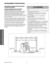
...sensors on both the leading and trailing edge. • If an edge sensor is recommended. • LiftMaster Monitored Entrapment Protection devices are for use with the photoelectric sensors model CPS-U, additional entrapment devices are available for...InInvviissiibblleeLLigighht tBeBaemam PrPotreoctteiocntiAorneaArea PhSoafteoteylRecevtreircsiSngensor 6"S(e1n5socrm) max. Right Side of its invisible light beam. The operator comes standard with LiftMaster Commercial Door Operators ONLY. When properly connected and aligned, the photoelectric sensors will stop and typically reverse to ...
...sensors on both the leading and trailing edge. • If an edge sensor is recommended. • LiftMaster Monitored Entrapment Protection devices are for use with the photoelectric sensors model CPS-U, additional entrapment devices are available for...InInvviissiibblleeLLigighht tBeBaemam PrPotreoctteiocntiAorneaArea PhSoafteoteylRecevtreircsiSngensor 6"S(e1n5socrm) max. Right Side of its invisible light beam. The operator comes standard with LiftMaster Commercial Door Operators ONLY. When properly connected and aligned, the photoelectric sensors will stop and typically reverse to ...
GT- Logic 4 Installation Manual
Page 22
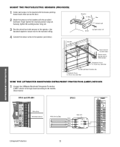
...oor WIRE THE LIFTMASTER MONITORED ENTRAPMENT PROTECTION (LMEP) DEVICES 1 Connect the LiftMaster Monitored Entrapment Protection (LMEP) device to the logic board according to the models shown below ). Securely tighten the sending sensor wing nut. 3 Run the wires from both sensors to the operator (see below ... with the lenses pointing toward each other across the door. 2 Attach the sensors to the brackets with insulated staples Connect wire to Operator (refer to following page) Photoelectric Sensor 6" (15 cm) max. above floor Invisible Light Beam Protection Area Photoelectric Sensor ...
...oor WIRE THE LIFTMASTER MONITORED ENTRAPMENT PROTECTION (LMEP) DEVICES 1 Connect the LiftMaster Monitored Entrapment Protection (LMEP) device to the logic board according to the models shown below ). Securely tighten the sending sensor wing nut. 3 Run the wires from both sensors to the operator (see below ... with the lenses pointing toward each other across the door. 2 Attach the sensors to the brackets with insulated staples Connect wire to Operator (refer to following page) Photoelectric Sensor 6" (15 cm) max. above floor Invisible Light Beam Protection Area Photoelectric Sensor ...


