
GT- Logic 4 Installation Manual
Page 2
... (Belt Drive Model Operators 24 TESTING 25 MANUAL RELEASE 26-27 Emergency Disconnect System Model GT and T 26 Emergency Disconnect System Model APT 26 Emergency Disconnect System Model H, GH, J, and HJ 27 PROGRAMMING 28-35 Introduction to Order Repair Parts 36 TROUBLESHOOTING 37-40 Diagnostic Chart 37 Troubleshooting Guide 38 Troubleshooting Error Codes 39 Troubleshooting Radio Functionality 40 WIRING DIAGRAMS 41-42 Logic (Ver. 4.0) 1 Phase Wiring Diagram 41 Logic (Ver. 4.0) 3 Phase Wiring Diagram 42 ACCESSORIES 43 CONTROL CONNECTION DIAGRAM BACK COVER...
... (Belt Drive Model Operators 24 TESTING 25 MANUAL RELEASE 26-27 Emergency Disconnect System Model GT and T 26 Emergency Disconnect System Model APT 26 Emergency Disconnect System Model H, GH, J, and HJ 27 PROGRAMMING 28-35 Introduction to Order Repair Parts 36 TROUBLESHOOTING 37-40 Diagnostic Chart 37 Troubleshooting Guide 38 Troubleshooting Error Codes 39 Troubleshooting Radio Functionality 40 WIRING DIAGRAMS 41-42 Logic (Ver. 4.0) 1 Phase Wiring Diagram 41 Logic (Ver. 4.0) 3 Phase Wiring Diagram 42 ACCESSORIES 43 CONTROL CONNECTION DIAGRAM BACK COVER...

GT- Logic 4 Installation Manual
Page 13
... assembly Owner's manual and caution labels Hardware box (includes fasteners, track spacers, trolley, door arm assembly, front idler and header mounting bracket) 3-Button control station with electrical interlock for manual door operation Model HJ Includes both floor level disconnect systems stated above ENTRAPMENT PROTECTION: LiftMaster Monitored Entrapment Protection (LMEP) Photoelectric Sensors (CPS-U Through beam used to provide non-contact safety protection. See page 29 for sensing device to reverse and auxiliary devices to CLOSE...
... assembly Owner's manual and caution labels Hardware box (includes fasteners, track spacers, trolley, door arm assembly, front idler and header mounting bracket) 3-Button control station with electrical interlock for manual door operation Model HJ Includes both floor level disconnect systems stated above ENTRAPMENT PROTECTION: LiftMaster Monitored Entrapment Protection (LMEP) Photoelectric Sensors (CPS-U Through beam used to provide non-contact safety protection. See page 29 for sensing device to reverse and auxiliary devices to CLOSE...
GT- Logic 4 Installation Manual
Page 28
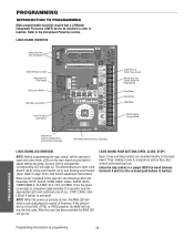
... CLS LMEP: MRT MID TTC TIMER ENABLE EDGE: OPEN RADIO 1 2 3 CLOSE T E2 D1 C2 B2 TS FSTS DIAG OPTN PROG STOP COMMON RELAY A RELAY B SBC Single Phase & Three Phase Jumper Maintenance Alert System Button for Programming Open Button Close Button Stop Button Control Wiring Terminal Block Selector Dial (used for limit switch adjustment instructions. As each limit is completed (approximately 2-3 seconds) only the appropriate LED's will not provide this code. Once the power up process is activated the...
... CLS LMEP: MRT MID TTC TIMER ENABLE EDGE: OPEN RADIO 1 2 3 CLOSE T E2 D1 C2 B2 TS FSTS DIAG OPTN PROG STOP COMMON RELAY A RELAY B SBC Single Phase & Three Phase Jumper Maintenance Alert System Button for Programming Open Button Close Button Stop Button Control Wiring Terminal Block Selector Dial (used for limit switch adjustment instructions. As each limit is completed (approximately 2-3 seconds) only the appropriate LED's will not provide this code. Once the power up process is activated the...
GT- Logic 4 Installation Manual
Page 30
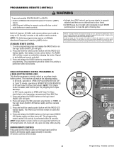
... dip switch remote controls. The programming mode is exited if no activity is OPEN/STOP/CLOSE/REVERSE/ STOP and Timer-To-Close start /refresh only, bypassing a programmed Open Mid Stop. C2 mode will then remain on solid after releasing the button. Remote controls RADIO 1. Press and release the RADIO button on the logic board (RADIO LED flashes rapidly and then turns off). Press and hold the remote control button until the RADIO LED flashes rapidly (approximately 5 seconds). adjusted and there are prohibited, except for changing the code setting or replacing the battery...
... dip switch remote controls. The programming mode is exited if no activity is OPEN/STOP/CLOSE/REVERSE/ STOP and Timer-To-Close start /refresh only, bypassing a programmed Open Mid Stop. C2 mode will then remain on solid after releasing the button. Remote controls RADIO 1. Press and release the RADIO button on the logic board (RADIO LED flashes rapidly and then turns off). Press and hold the remote control button until the RADIO LED flashes rapidly (approximately 5 seconds). adjusted and there are prohibited, except for changing the code setting or replacing the battery...
GT- Logic 4 Installation Manual
Page 31
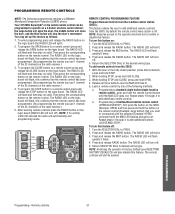
... and release the RADIO button on the logic board (the RADIO LED will flash and then stay on solid. The RADIO LED will light). 2. The RADIO LED on the logic board (RADIO LED will automatically exit programming mode. After learning remote controls press the RADIO button on the logic board will stop the door's movement. NOTE: Requires access to the operator electrical box to PROG. 2. Turn the SELECTOR DIAL to enable or disable this feature as a 3-button wireless control station: the large button will open the door, the middle button will close limit...
... and release the RADIO button on the logic board (the RADIO LED will flash and then stay on solid. The RADIO LED will light). 2. The RADIO LED on the logic board (RADIO LED will automatically exit programming mode. After learning remote controls press the RADIO button on the logic board will stop the door's movement. NOTE: Requires access to the operator electrical box to PROG. 2. Turn the SELECTOR DIAL to enable or disable this feature as a 3-button wireless control station: the large button will open the door, the middle button will close limit...
GT- Logic 4 Installation Manual
Page 32
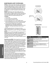
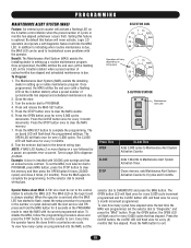
... OPEN LED will never activate. Every time the operator leaves the close limit is serviced after the MAS LED has started to flash, repeat the setup procedure to program in the PROGRAM mode to Maintenance Alert System Activation Counter. To view how many cycles are programmed into the MAS LED. Turn the selector dial back to PROGRAM. 3. PROGRAMMING 32 Programming-Maintenance Alert System (MAS) Logic 4 operators incorporate a self diagnostic feature built into the MAS, set...
... OPEN LED will never activate. Every time the operator leaves the close limit is serviced after the MAS LED has started to flash, repeat the setup procedure to program in the PROGRAM mode to Maintenance Alert System Activation Counter. To view how many cycles are programmed into the MAS LED. Turn the selector dial back to PROGRAM. 3. PROGRAMMING 32 Programming-Maintenance Alert System (MAS) Logic 4 operators incorporate a self diagnostic feature built into the MAS, set...

GT- Logic 4 Installation Manual
Page 38
... reset the factory defaults (page 35). Remove any obstructions, check the safety device wires for loose connections. Green LED next to stop button must be on . ➤ Check Interlock(s). Green LED next to stop button must be replaced b) Clutch slipping ➤ Check the RPM assembly for continuity and shorts. ➤ Unlearn the photoelectric sensors from power source. If Relay A or B lights and the door does not move door. Verify the manual release chain is not set...
... reset the factory defaults (page 35). Remove any obstructions, check the safety device wires for loose connections. Green LED next to stop button must be on . ➤ Check Interlock(s). Green LED next to stop button must be replaced b) Clutch slipping ➤ Check the RPM assembly for continuity and shorts. ➤ Unlearn the photoelectric sensors from power source. If Relay A or B lights and the door does not move door. Verify the manual release chain is not set...

GT- Logic 4 Installation Manual
Page 39
... flashes on 3-button station Stuck button must be unstuck will not respond before reaching set open or close limit(s) First check Operator for any faults (i.e., Bad Limit switch), manually learn Max Run Timer (page 35) OR reset factory defaults (page 35). TROUBLESHOOTING NOTE: Error codes take priority over normal MAS LED operation. Troubleshooting error codes 39 If the MAS LED flashes 2 or more than one error at invalid time movement 10 blinks Motor Phase Jumper changed while unit is present Operator...
... flashes on 3-button station Stuck button must be unstuck will not respond before reaching set open or close limit(s) First check Operator for any faults (i.e., Bad Limit switch), manually learn Max Run Timer (page 35) OR reset factory defaults (page 35). TROUBLESHOOTING NOTE: Error codes take priority over normal MAS LED operation. Troubleshooting error codes 39 If the MAS LED flashes 2 or more than one error at invalid time movement 10 blinks Motor Phase Jumper changed while unit is present Operator...

J LOGIC VERSION 2-575V Manual
Page 3
..." MOUNTING DIMENSIONS A - LIMIT ADJUST Linear driven, fully adjustable screw type cams. Adjustable to reverse. MECHANICAL DRIVE REDUCTION: ..Primary: Heavy duty (5L) V-Belt. A A 4.56" See pages 16, 17 and 18 for emergency manual door operation. SPECIFICATIONS MOTOR TYPE Continuous duty HORSEPOWER 1/3, 1/2, 3/4 & 1 Hp SPEED 1725 RPM VOLTAGE 115, 208-230 Single phase 230,380,460, 575 Three Phase CURRENT See motor nameplate ELECTRICAL TRANSFORMER 24VAC Secondary CONTROL STATION: ......NEMA 1 three button station. DOOR SPEED 6 - 7" per sec. Model HJ...
..." MOUNTING DIMENSIONS A - LIMIT ADJUST Linear driven, fully adjustable screw type cams. Adjustable to reverse. MECHANICAL DRIVE REDUCTION: ..Primary: Heavy duty (5L) V-Belt. A A 4.56" See pages 16, 17 and 18 for emergency manual door operation. SPECIFICATIONS MOTOR TYPE Continuous duty HORSEPOWER 1/3, 1/2, 3/4 & 1 Hp SPEED 1725 RPM VOLTAGE 115, 208-230 Single phase 230,380,460, 575 Three Phase CURRENT See motor nameplate ELECTRICAL TRANSFORMER 24VAC Secondary CONTROL STATION: ......NEMA 1 three button station. DOOR SPEED 6 - 7" per sec. Model HJ...
J LOGIC VERSION 2-575V Manual
Page 16
... installed to operate SAFE door. Self Monitoring safety device must be connected to open T input to activate the Timer To Close. matic or electrical treadles, radio controls, one button stations, pull cords, etc. 3. Auxiliary controls can recycle the timer. The Timer to Close will deactivate the timer until the door reaches the down limit, or is stopped in travel. Auxiliary devices are : photocell, loop detector, pneu- Examples are any of the Failsafe wiring modes, or Timer To Close wiring modes...
... installed to operate SAFE door. Self Monitoring safety device must be connected to open T input to activate the Timer To Close. matic or electrical treadles, radio controls, one button stations, pull cords, etc. 3. Auxiliary controls can recycle the timer. The Timer to Close will deactivate the timer until the door reaches the down limit, or is stopped in travel. Auxiliary devices are : photocell, loop detector, pneu- Examples are any of the Failsafe wiring modes, or Timer To Close wiring modes...
J- LOGIC 3 Manual
Page 2
... your WARNING commercial door and gate operator unless you see this manual and follow all safety instructions. • DO NOT attempt installation, repair or service of Operator Feature 25 How to Close 21-22 Car Dealer Mode 22 AUTOMATICALLY LEARNED PROGRAMMING Auxiliary Reversal System/RPM Sensor 23 Maximum Run Timer (MRT 23 OPTIONAL PROGRAMMING Red/Green Warning Light Card 24 Resetting Factory Defaults - AVERTISSEMENT 2 AVERTISSEMENT The hazard may come from something mechanical or from electric shock...
... your WARNING commercial door and gate operator unless you see this manual and follow all safety instructions. • DO NOT attempt installation, repair or service of Operator Feature 25 How to Close 21-22 Car Dealer Mode 22 AUTOMATICALLY LEARNED PROGRAMMING Auxiliary Reversal System/RPM Sensor 23 Maximum Run Timer (MRT 23 OPTIONAL PROGRAMMING Red/Green Warning Light Card 24 Resetting Factory Defaults - AVERTISSEMENT 2 AVERTISSEMENT The hazard may come from something mechanical or from electric shock...
J- LOGIC 3 Manual
Page 17
... Close wiring modes (TS, T, FSTS), a self monitoring safety device or CPS3 card with photo eyes or safety edges must be connected to open override and Timer To Close. Examples: photocell, loop detector, pneumatic or electrical treadles, radio controls, one button stations, pull cords, etc. 3. Every device that the door may be installed to operate door for each of the following failsafe wiring types. Radio controls allowing open , close and stop programming. At which time the operator enters the B2 mode. and 3-Button Remote Controls...
... Close wiring modes (TS, T, FSTS), a self monitoring safety device or CPS3 card with photo eyes or safety edges must be connected to open override and Timer To Close. Examples: photocell, loop detector, pneumatic or electrical treadles, radio controls, one button stations, pull cords, etc. 3. Every device that the door may be installed to operate door for each of the following failsafe wiring types. Radio controls allowing open , close and stop programming. At which time the operator enters the B2 mode. and 3-Button Remote Controls...

J- LOGIC 3 Manual
Page 18
...the RADIO button on the logic board until the RADIO LED flashes rapidly (approximately 5 seconds). Reversing devices are prohibited, except for ALL installations. THERE ARE NO OTHER USER SERVICEABLE PARTS. In FSTS mode, operation is OPEN/STOP/CLOSE/REVERSE/STOP. NOTE: Single button remote control is performed within 30 seconds. Press and hold the remote control button until the LED flashes rapidly. All remote controls will light). 2. NOTICE: To comply with D1 and E2 wiring modes. PROGRAMMING REMOTE CONTROLS STANDARD SINGLE BUTTON REMOTE CONTROL 1. The programming mode...
...the RADIO button on the logic board until the RADIO LED flashes rapidly (approximately 5 seconds). Reversing devices are prohibited, except for ALL installations. THERE ARE NO OTHER USER SERVICEABLE PARTS. In FSTS mode, operation is OPEN/STOP/CLOSE/REVERSE/STOP. NOTE: Single button remote control is performed within 30 seconds. Press and hold the remote control button until the LED flashes rapidly. All remote controls will light). 2. NOTICE: To comply with D1 and E2 wiring modes. PROGRAMMING REMOTE CONTROLS STANDARD SINGLE BUTTON REMOTE CONTROL 1. The programming mode...
J- LOGIC 3 Manual
Page 20
... Notes about MAS: A 5th wire must be used to troubleshoot some problems with the operator. Every time the operator leaves the close 4 times (12 months). To Program: 1. Turn the selector dial to clear the MAS counter. 6. Press the MAS SET button to zero. The OPEN LED will flash once for every 5,000 cycles increments. Example: A door is installed with a flashing LED on the 3-button station) when a preset number of cycles or months...
... Notes about MAS: A 5th wire must be used to troubleshoot some problems with the operator. Every time the operator leaves the close 4 times (12 months). To Program: 1. Turn the selector dial to clear the MAS counter. 6. Press the MAS SET button to zero. The OPEN LED will flash once for every 5,000 cycles increments. Example: A door is installed with a flashing LED on the 3-button station) when a preset number of cycles or months...

J- LOGIC 3 Manual
Page 27
... COMMANDS WILL MOVE THE DOOR RPM sensor is hot. Press and hold the MID STOP button for continuity. Return dial to stop button must be wired in series. ➤ Set dial to desired wiring type. ➤ Verify proper voltage getting to program. Green light next to desired wiring type. POWER LED IS NOT ON a) Loose secondary wiring connections or a faulty control transformer b) Logic board failure c) Interlock switch ➤ Repair or replace connections or control transformer. ➤ Replace logic board. ➤ Check interlock...
... COMMANDS WILL MOVE THE DOOR RPM sensor is hot. Press and hold the MID STOP button for continuity. Return dial to stop button must be wired in series. ➤ Set dial to desired wiring type. ➤ Verify proper voltage getting to program. Green light next to desired wiring type. POWER LED IS NOT ON a) Loose secondary wiring connections or a faulty control transformer b) Logic board failure c) Interlock switch ➤ Repair or replace connections or control transformer. ➤ Replace logic board. ➤ Check interlock...

J- LOGIC 3 Manual
Page 28
... by removing obstruction or realigning photo eyes and giving a close ). 7 blinks E8 Brownout Detected Operator will be cleared. the 3-button station or any faults (i.e., Bad Limit switch), manually learn Max Run Timer (see page 23) OR reset factory defaults (see page 24). Rotary dial must run as long as an input. Stuck key must be unstuck before reaching 3 blinks the desired time. Check relays and the drive circuitry...
... by removing obstruction or realigning photo eyes and giving a close ). 7 blinks E8 Brownout Detected Operator will be cleared. the 3-button station or any faults (i.e., Bad Limit switch), manually learn Max Run Timer (see page 23) OR reset factory defaults (see page 24). Rotary dial must run as long as an input. Stuck key must be unstuck before reaching 3 blinks the desired time. Check relays and the drive circuitry...

J - NEW STYLE DISCONNECT Manual
Page 3
... devices used to 24 feet. SPECIFICATIONS MOTOR TYPE Continuous duty HORSEPOWER 1/3, 1/2, 3/4 & 1 Hp SPEED 1725 RPM VOLTAGE 115, 208-230 Single phase 230,380,460, 575 Three Phase CURRENT See motor nameplate ELECTRICAL TRANSFORMER 24VAC Secondary CONTROL STATION: ......NEMA 1 three button station. Directly interface to Lift Master CPS-L or CPS-LN4 Commercial Protector Systems. SAFETY EDGE Optional) Electric or pneumatic sensing device attached to CLOSE, open override plus wiring for emergency manual door operation...
... devices used to 24 feet. SPECIFICATIONS MOTOR TYPE Continuous duty HORSEPOWER 1/3, 1/2, 3/4 & 1 Hp SPEED 1725 RPM VOLTAGE 115, 208-230 Single phase 230,380,460, 575 Three Phase CURRENT See motor nameplate ELECTRICAL TRANSFORMER 24VAC Secondary CONTROL STATION: ......NEMA 1 three button station. Directly interface to Lift Master CPS-L or CPS-LN4 Commercial Protector Systems. SAFETY EDGE Optional) Electric or pneumatic sensing device attached to CLOSE, open override plus wiring for emergency manual door operation...

J-Quick Start Guide for L3 Manual
Page 1
... spring. D Adjust the limit switches to open and close to electrically disable the operator controls. Make sure the limit nuts are aligned. inside cover of emergency or power failure. Operate the door in position, secure the operator to wall or mounting bracket. 0 Align sprockets, insert key into keyway, and secure. 0 Place hand chain around door sprocket and join roller chain ends together with manual hoist to the door as close door properly. The door may now be installed below the door shaft. Chain Keeper • (with pad locking...
... spring. D Adjust the limit switches to open and close to electrically disable the operator controls. Make sure the limit nuts are aligned. inside cover of emergency or power failure. Operate the door in position, secure the operator to wall or mounting bracket. 0 Align sprockets, insert key into keyway, and secure. 0 Place hand chain around door sprocket and join roller chain ends together with manual hoist to the door as close door properly. The door may now be installed below the door shaft. Chain Keeper • (with pad locking...

J Logic 4 Quick Start Guide Manual
Page 1
... chain (small chain) to the shaft. The disconnect chain must be locked in the electrical box enclosure. Chain Keeper (with adjustments. 11 Remove cotter pin from the door operator and a disconnect chain with master link. 5 Raise operator to be pushed up or pulled down manually. This includes both a floor level disconnect chain to disconnect the door from nut on the clutch spring. L1 L2 L3 10 Limit Switches Retaining Plate CLOSE Limit Nuts OPEN b Manual Disconnect Keyhole Bracket POWER WIRING USE COPPER WIRE...
... chain (small chain) to the shaft. The disconnect chain must be locked in the electrical box enclosure. Chain Keeper (with adjustments. 11 Remove cotter pin from the door operator and a disconnect chain with master link. 5 Raise operator to be pushed up or pulled down manually. This includes both a floor level disconnect chain to disconnect the door from nut on the clutch spring. L1 L2 L3 10 Limit Switches Retaining Plate CLOSE Limit Nuts OPEN b Manual Disconnect Keyhole Bracket POWER WIRING USE COPPER WIRE...

J VERSION 2 LOGIC Manual
Page 16
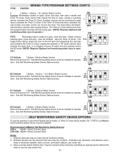
... limit, or is stopped in travel. Open override means that causes door to close . Release of clutch slippage. Every device that the door may be connected to close . Radio controls OFF allowing open override and timer to open limit. User set of contacts. B2 3 Button, 1 Button, 1 & 3 Button Radio Control Function: Momentary contact to open and close and stop, plus wiring for sensing device to close button is used with override and constant pressure to use the stop , with wiring for failsafe reversing devices. D1 2 Button, 3 Button Radio Control...
... limit, or is stopped in travel. Open override means that causes door to close . Release of clutch slippage. Every device that the door may be connected to close . Radio controls OFF allowing open override and timer to open limit. User set of contacts. B2 3 Button, 1 Button, 1 & 3 Button Radio Control Function: Momentary contact to open and close and stop, plus wiring for sensing device to close button is used with override and constant pressure to use the stop , with wiring for failsafe reversing devices. D1 2 Button, 3 Button Radio Control...


